Toyota Tacoma (2015-2018) Service Manual: Terminals Of Ecu
TERMINALS OF ECU
1. CHECK 4 WHEEL DRIVE CONTROL ECU
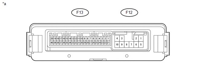 Text in Illustration
|
*a |
Component with harness connected (4 Wheel Drive Control ECU) |
- |
- |
(a) Measure the resistance and voltage according to the value(s) in the table below.
|
Terminal No. (Symbol) |
Wiring Color |
Terminal Description |
Condition |
Specified Condition |
|---|---|---|---|---|
|
F13-12 (SLS) - F12-10 (GND) |
L - W-B |
Differential lock indicator switch |
Ignition switch ON Rear differential FREE |
10 to 14 V |
|
Ignition switch ON Rear differential LOCK |
Below 1.5 V |
|||
|
F13-15 (R) - F12-10 (GND) |
R - W-B |
Differential lock switch input |
Ignition switch ON Differential lock switch not pressed |
11 to 14 V |
|
Ignition switch ON Differential lock switch pressed and held |
Below 1.5 V |
|||
|
F13-20 (CANH) - F13-40 (CANL) |
BE - W |
HIGH-level CAN bus wire - LOW-level CAN bus wire |
Ignition switch off Cable disconnected from negative (-) battery terminal |
54 to 69 Ω |
|
F13-21 (+B) - F12-10 (GND) |
W - W-B |
ECU power supply |
Always |
10 to 14 V |
|
F12-1 (SL+) - F12-10 (GND) |
B - W-B |
Differential lock coil drive output (continuity with IG when operating) |
Ignition switch ON Rear differential free |
Below 1.5 V |
|
Ignition switch ON Switching between free and locked (Condition: A or C) |
Pulse generation (See waveform 1) |
|||
|
Ignition switch ON Rear differential locked (Condition B) |
Pulse generation (See waveform 1) |
|||
|
F12-4 (IG) - F12-10 (GND) |
Y - W-B |
ECU and actuator power supply |
Ignition switch ON |
11 to 14 V |
|
F12-5 (SL-) - F12-10 (GND) |
W - W-B |
Differential lock coil drive output (continuity with GND when operating) |
Ignition switch ON Rear differential free |
Below 1.5 V |
|
Ignition switch ON Rear differential switching between free and locked (Condition: A or C) |
Pulse generation (See waveform 2) |
|||
|
Ignition switch ON Rear differential locked (Condition B) |
Pulse generation (See waveform 2) |
|||
|
F12-10 (GND) - Body ground |
W-B - Body ground |
Ground |
Always |
Below 1 Ω |
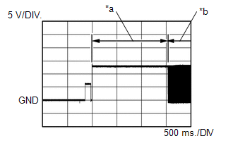
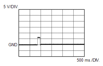
(b) Waveform 1
(1) Rear differential in locked condition
|
Item |
Content |
|---|---|
|
Tester Connection |
F12-1 (SL+) - F12-10 (GND) |
|
Tool Setting |
5 V/DIV., 500 ms./DIV. |
|
Condition: A |
Ignition switch ON Switching between free and locked |
|
Condition: B |
Ignition switch ON Rear differential locked |
|
*a |
Condition: A |
|
*b |
Condition: B |
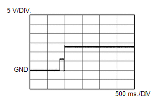
(2) Rear differential not in locked condition (switching between free and locked)
|
Item |
Content |
|---|---|
|
Tester Connection |
F12-1 (SL+) - F12-10 (GND) |
|
Tool Setting |
.5 V/DIV., 500 ms./DIV. |
|
Condition: C |
Ignition switch ON Switching between free and locked |
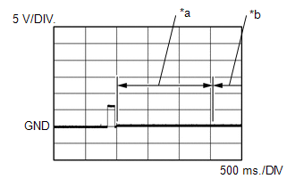
(c) Waveform 2
(1) Rear differential in locked condition
|
Item |
Content |
|---|---|
|
Tester Connection |
F12-5 (SL-) - F12-10 (GND) |
|
Tool Setting |
5 V/DIV., 500 ms./DIV. |
|
Condition: A |
Ignition switch ON Switching between free and locked |
|
Condition: B |
Ignition switch ON Rear differential locked |
|
*a |
Condition: A |
|
*b |
Condition: B |
(2) Rear differential not in locked condition (switching between free and locked)
|
Item |
Content |
|---|---|
|
Tester Connection |
F12-5 (SL-) - F12-10 (GND) |
|
Tool Setting |
5 V/DIV., 500 ms./DIV. |
|
Condition: C |
Ignition switch ON Switching between free and locked |
 Diagnosis System
DIAGNOSIS SYSTEM
1. DESCRIPTION
The 4 wheel drive control ECU records DTCs when the ECU detects a malfunction
in the ECU itself or in system circuits.
The DTCs can be read through the DLC3 of the ...
 Dtc Check / Clear
DTC CHECK / CLEAR
1. CHECK DTC
(a) Check the DTCs.
(1) Turn the ignition switch off.
(2) Connect the Techstream to the DLC3.
(3) Turn the ignition switch to ON.
(4) Turn the Techstream on.
(5) ...
Other materials:
IG Power Source Circuit
DESCRIPTION
The main power source is supplied to the air conditioning amplifier assembly
when the ignition switch is turned to ON.
The power is used for operating the air conditioning amplifier assembly, servo
motors, etc.
WIRING DIAGRAM
CAUTION / NOTICE / HINT
NOTICE:
Inspect the fuses ...
Terminals Of Ecm
TERMINALS OF ECM
1. CHECK ECM
HINT:
The standard normal voltage between each pair of ECM terminals is shown in the
table below. The appropriate conditions for checking each pair of terminals are
also indicated. The result of checks should be compared with the standard normal
voltage for t ...
Freeze Frame Data
FREEZE FRAME DATA
DESCRIPTION
(a) Whenever a forward recognition camera system DTC is stored, the forward recognition
camera stores the current vehicle state (ECU and sensor information) as Freeze Frame
Data.
CHECK FREEZE FRAME DATA
(a) Connect the Techstream to the DLC3.
(b) Turn the ignit ...
