Toyota Tacoma (2015-2018) Service Manual: Reassembly
REASSEMBLY
CAUTION / NOTICE / HINT
CAUTION:
Wear protective gloves. Sharp areas on the parts may injure your hands.
PROCEDURE
1. INSTALL SEPARATE TYPE REAR SEATBACK COVER
|
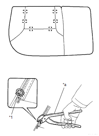
(a) Using hog ring pliers, install the separate type rear seatback cover with 2 new hog rings. Text in Illustration
NOTICE:
|
|
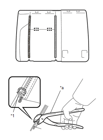
(b) Engage the 2 hook-and-loop fasteners.
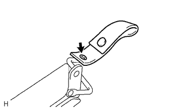
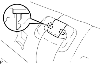
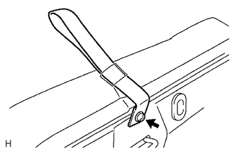
2. INSTALL REAR SEAT LOCK HANDLE
|
(a) Install the rear seat lock handle with the screw. |
|
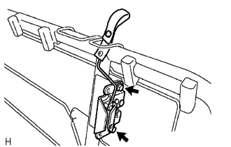
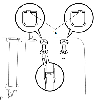
3. INSTALL REAR SEATBACK LOCK ASSEMBLY
|
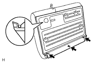
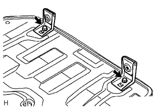
(a) Install the rear seatback lock assembly with the 2 bolts. Torque: 30 N·m {306 kgf·cm, 22 ft·lbf} |
|
4. INSTALL REAR CENTER SEAT OUTER BELT ASSEMBLY
.gif)
5. INSTALL CENTER SEATBACK PAD
6. INSTALL REAR SEATBACK FRAME SUB-ASSEMBLY
|
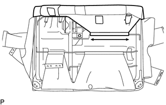
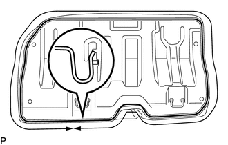
(a) Engage the 2 hooks to install the rear seatback frame sub-assembly. |
|
|
(b) Engage the 2 hooks. |
|
7. INSTALL REAR SEAT SHOULDER BELT COVER
|
(a) Engage the 4 claws to install the rear seat shoulder belt cover. |
|
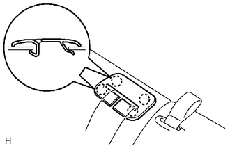
8. INSTALL SEAT BELT ANCHOR COVER CAP
|
(a) Engage the 2 claws to install the seat belt anchor cover cap. |
|
9. INSTALL REAR NO. 1 SEAT HEADREST SUPPORT ASSEMBLY
|
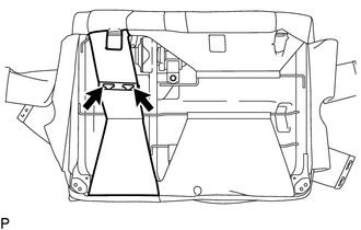
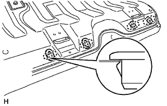
(a) Engage the protrusion of the rear No. 1 seat headrest support assemblies with the groove in the installation portion of the rear seatback frame sub-assembly. Text in Illustration
|
|
(b) Engage the 4 claws to install the 2 rear No. 1 seat headrest support assemblies.
10. INSTALL REAR SEAT HEADREST SUPPORT
|
(a) Engage the 4 claws to install the 2 rear seat headrest supports. |
|
.png)
|
(b) Engage the hook. |
|
|
(c) Connect the rear seatback cover strap. |
|
|
(d) Connect the 2 rear seatback cover straps. |
|
11. INSTALL REAR SEATBACK BOARD SUB-ASSEMBLY
|
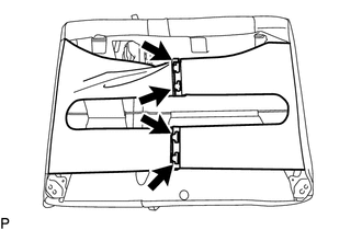
(a) Engage the 5 claws and install the rear seatback board sub-assembly. |
|
(b) Install the 3 screws.
12. INSTALL REAR SEAT HEADREST ASSEMBLY
(a) Disengage the 2 lock buttons of the 2 rear seat headrest supports to install the rear seat headrest assembly.
13. INSTALL REAR CENTER SEAT HEADREST ASSEMBLY
(a) Disengage the lock button of the rear No. 1 seat headrest support assembly to install the rear center seat headrest assembly.
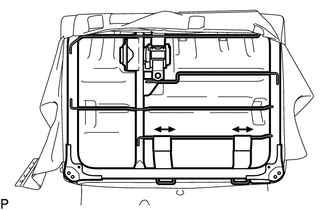
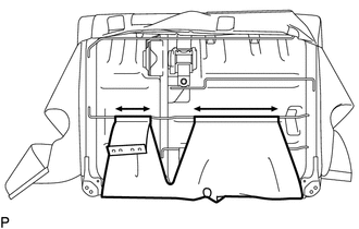
14. INSTALL SEPARATE TYPE REAR SEAT CUSHION COVER
|
(a) Using hog ring pliers, install the separate type rear seat cushion cover with 6 new hog rings. Text in Illustration
NOTICE:
|
|
15. INSTALL REAR SEAT CUSHION FRAME SUB-ASSEMBLY
|
(a) Engage the hook and install the rear seat cushion frame sub-assembly. |
|
16. INSTALL REAR SEAT CUSHION HINGE SUB-ASSEMBLY
|
(a) Install the 2 rear seat cushion hinge sub-assemblies with the 2 bolts. Torque: 21 N·m {214 kgf·cm, 15 ft·lbf} |
|
17. INSTALL REAR SEAT HEADREST HOLDER
|
(a) Engage the 8 claws to install the 4 rear seat headrest holders. |
|
18. INSTALL REAR SEAT CUSHION BAND
|
(a) Install the rear seat cushion band with the screw. |
|
 Installation
INSTALLATION
PROCEDURE
1. INSTALL REAR SEATBACK HINGE SUB-ASSEMBLY
(a) Install the rear seatback hinge sub-assembly with the 2 bolts.
Torque:
30 N·m {306 kgf·cm, 22 ft·lbf}
2. INSTALL REAR S ...

Other materials:
Installation
INSTALLATION
PROCEDURE
1. INSTALL TRANSMISSION WIRE
(a) Coat 2 new O-rings with ATF, and install them to the 2 temperature sensors.
(b) Coat a new O-ring with ATF, and install it to the transmission wire.
(c) Install the transmission wire to the automatic transmission case sub-assembly
with t ...
On-vehicle Inspection
ON-VEHICLE INSPECTION
PROCEDURE
1. INSPECT SIDE AIRBAG SENSOR ASSEMBLY (for Vehicle not Involved in Collision)
(a) Perform a diagnostic system check (See page
).
2. INSPECT SIDE AIRBAG SENSOR ASSEMBLY (for Vehicle Involved in Collision and
Airbag has not Deployed)
(a) Perform a diagnostic s ...
Turn signal lever
Right turn
Left turn
Move and hold the lever partway to
signal a lane change.
The right hand signal will flash until you release the lever.
Move and hold the lever partway
to signal a lane change.
The left hand signal will flash until you release the lever.
■Turn signals can be ...
