Toyota Tacoma (2015-2018) Service Manual: Removal
REMOVAL
PROCEDURE
1. REMOVE REAR SEAT CUSHION ASSEMBLY
.gif)
2. REMOVE NO. 4 ROOM PARTITION COVER LH
3. REMOVE NO. 4 ROOM PARTITION COVER RH
4. REMOVE NO. 3 ROOM PARTITION COVER
5. REMOVE BACK PANEL GARNISH HOLE PLUG
6. REMOVE BACK PANEL TRIM
7. REMOVE FRONT DOOR SCUFF PLATE
8. REMOVE REAR DOOR SCUFF PLATE
9. DISCONNECT FRONT DOOR OPENING TRIM WEATHERSTRIP
|
(a) Disconnect the front door opening trim weatherstrip to the extent which allows the removal of the roof side garnish inner, quarter trim lower panel and quarter inside trim board. |
|
10. REMOVE ROOF SIDE INNER GARNISH CAP
11. REMOVE ROOF SIDE INNER GARNISH
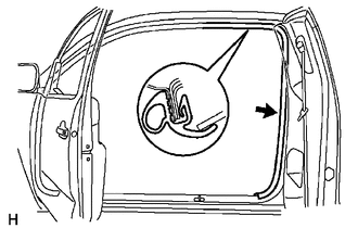
12. DISCONNECT REAR SEAT 3 POINT TYPE OUTER BELT ASSEMBLY
13. REMOVE QUARTER TRIM LOWER PANEL
14. REMOVE QUARTER INSIDE TRIM BOARD
15. REMOVE REAR SEAT 3 POINT TYPE OUTER BELT ASSEMBLY
|
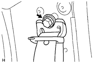
(a) Loosen the bolt to disconnect the shoulder anchor. |
|
|
(b) Remove the bolt. |
|
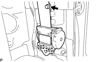
(c) Disengage the 2 guides to remove the rear seat 3 point type outer belt assembly.
 Installation
INSTALLATION
PROCEDURE
1. INSTALL REAR SEAT 3 POINT TYPE OUTER BELT ASSEMBLY
(a) Before installing the rear seat 3 point type outer belt assembly,
check the ELR function.
Text in ...

Other materials:
Manual Shifting Test
MANUAL SHIFTING TEST
1. PERFORM MANUAL SHIFTING TEST
HINT:
Using this test, it can be determined whether a problem is in an electrical
circuit or if it is a mechanical problem in the transmission.
If any abnormalities are found in the following test, the problem is
in the tran ...
Rear Console Box
Components
COMPONENTS
ILLUSTRATION
ILLUSTRATION
Installation
INSTALLATION
PROCEDURE
1. INSTALL BOX BOTTOM MAT
(a) Engage the 10 guides and install the 2 box bottom mats.
2. INSTALL CONSOLE BOX PLATE
(a) Engage the 2 guides and install the console box plate.
(b) Install the 6 screw ...
Disposal
DISPOSAL
CAUTION / NOTICE / HINT
CAUTION:
Before performing pre-disposal deployment of any SRS part, review and closely
follow all applicable environmental and hazardous material regulations. Predisposal
deployment may be considered hazardous material treatment.
PROCEDURE
1. PRECAUTION
...
