Toyota Tacoma (2015-2018) Service Manual: System Diagram
SYSTEM DIAGRAM
 Parts Location
PARTS LOCATION
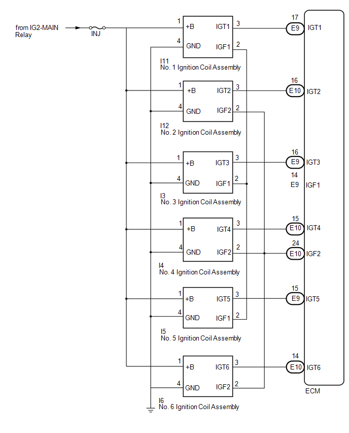
ILLUSTRATION
ILLUSTRATION
ILLUSTRATION
...
 On-vehicle Inspection
ON-VEHICLE INSPECTION
CAUTION / NOTICE / HINT
HINT:
Perform "Inspection After Repair" after replacing an ignition coil assembly or
spark plug (See page ).
PROCEDURE
1. PERFORM SPARK ...
Other materials:
Data List / Active Test
DATA LIST / ACTIVE TEST
DATA LIST
NOTICE:
In the table below, the values listed under "Normal Condition" are reference
values. Do not depend solely on these reference values when deciding whether a part
is faulty or not.
HINT:
Using the Techstream to read the Data List allows the ...
ECU Malfunction (B1003)
DESCRIPTION
DTC No.
DTC Detection Condition
Trouble Area
B1003
A malfunction in the non-volatile storage of the central gateway ECU
(network gateway ECU) is detected.
Central gateway ECU (network gateway ECU)
PROC ...
Instrument panel
*1: 4WD models only
*2: If equipped
*3: Vehicles with a manual transmission
*: Refer to “NAVIGATION SYSTEM OWNER’S MANUAL”.
*1: If equipped
*2: 4WD models only ...
