Toyota Tacoma (2015-2018) Service Manual: Parts Location
PARTS LOCATION
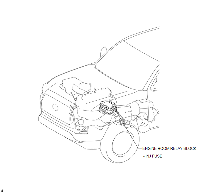
ILLUSTRATION
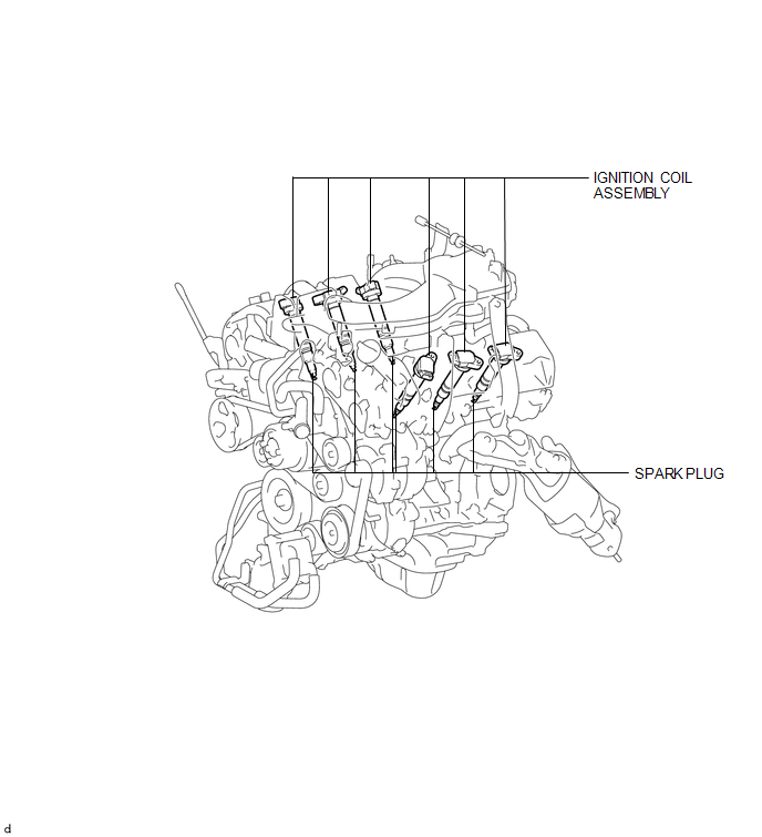
ILLUSTRATION
ILLUSTRATION
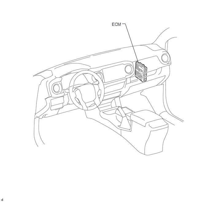
 Ignition System
...
 System Diagram
SYSTEM DIAGRAM
...
Other materials:
Side Turn Signal Light Assembly
Components
COMPONENTS
ILLUSTRATION
Removal
REMOVAL
CAUTION / NOTICE / HINT
HINT:
Use the same procedure for both the RH and LH sides.
The procedure described below is for the LH side.
PROCEDURE
1. REMOVE OUTER REAR VIEW MIRROR ASSEMBLY
(See page )
2. REMOVE OUTER ...
Microphone Amplifier
Components
COMPONENTS
ILLUSTRATION
*A
w/o Sliding Roof
*B
w/ Sliding Roof
*1
TELEPHONE MICROPHONE ASSEMBLY
-
-
Removal
REMOVAL
PROCEDURE
1. REMOVE ROOF HEADLINING ASSEMBLY (for Double ...
Position Initialization Incomplete (B2343)
DESCRIPTION
This DTC is stored when the sliding roof ECU (sliding roof drive gear sub-assembly)
has not been initialized.
DTC No.
DTC Detection Condition
Trouble Area
B2343
Sliding roof ECU (sliding roof drive gear sub-assembly) has no ...
