Toyota Tacoma (2015-2018) Service Manual: Front Passenger Side Power Window does not Operate with Front Passenger Side Power Window Switch
DESCRIPTION
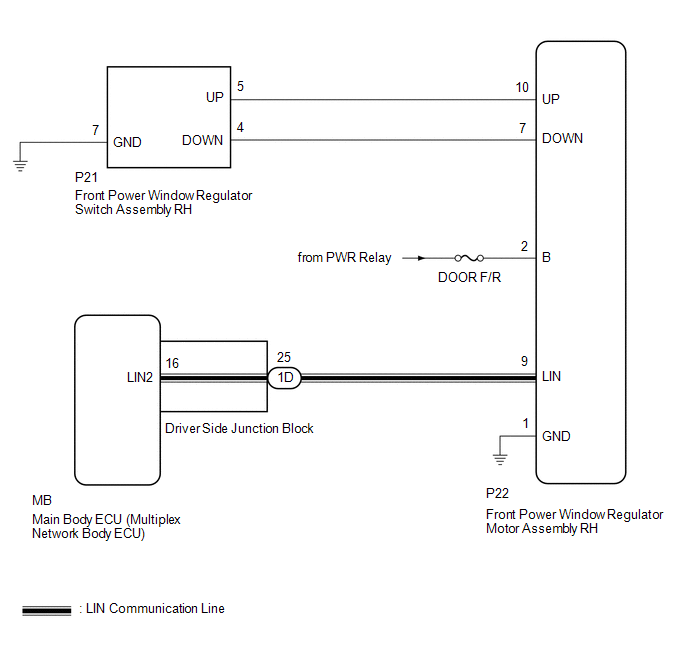
When the engine is running or the ignition switch is ON, the front power window regulator motor assembly RH is operated by the front power window regulator switch assembly RH. The front power window regulator motor assembly RH has motor, regulator, and ECU functions.
HINT:
If the pulse sensor built into the front power window regulator motor assembly RH malfunctions, the power window control system enters fail-safe mode. The remote up/down and auto up/down functions cannot be operated during fail-safe mode. However, the power window can be closed by holding the front power window regulator switch assembly RH at the auto up position, and opened manually by pushing down the front power window regulator switch assembly RH.
WIRING DIAGRAM
CAUTION / NOTICE / HINT
NOTICE:
- The power window control system uses the LIN communication system. Inspect
the communication function by following How to Proceed with Troubleshooting.
Troubleshoot the power window control system after confirming that the communication
system is functioning properly (See page
.gif) ).
). - If the front power window regulator motor assembly RH has been replaced
with a new one, initialize the power window control system (See page
).
- Check that the window lock switch is off before performing the following procedure.
- Inspect the fuses for circuits related to this system before performing the following procedure.
PROCEDURE
|
1. |
READ VALUE USING TECHSTREAM (MAIN BODY) |
(a) Connect the Techstream to the DLC3.
(b) Turn the ignition switch to ON.
(c) Turn the Techstream on.
(d) Enter the following menus: Body Electrical / Main Body / Data List.
(e) Read the Data List according to the display on the Techstream.
Main Body (Main Body ECU)|
Tester Display |
Measurement Item/Range |
Normal Condition |
Diagnostic Note |
|---|---|---|---|
|
Communication P-Door Motor |
Connection status between front power window regulator motor assembly RH and main body ECU / OK or STOP |
OK: Normal communication STOP: Communication stopped |
- |
OK:
On the Techstream screen, OK is displayed.
| NG | .gif) |
GO TO LIN COMMUNICATION SYSTEM (Proceed to How to Proceed with Troubleshooting) |
|
.gif)
|
2. |
READ VALUE USING TECHSTREAM (P-DOOR MOTOR) |
(a) Enter the following menus: Body Electrical / P-Door Motor / Data List.
(b) Read the Data List according to the display on the Techstream.
P-Door Motor (Front Power Window Regulator Motor Assembly RH)|
Tester Display |
Measurement Item/Range |
Normal Condition |
Diagnostic Note |
|---|---|---|---|
|
P Door P/W Up SW |
Front passenger side power window manual up switch signal / ON or OFF |
ON: Front passenger side power window manual up switch operated OFF: Front passenger power window manual up switch not operated |
- |
|
P Door P/W Down SW |
Front passenger side power window manual down switch signal / ON or OFF |
ON: Front passenger side power window manual down switch operated OFF: Front passenger power window manual down switch not operated |
- |
OK:
On the Techstream screen, ON or OFF is displayed accordingly.
| NG | |
GO TO STEP 4 |
|
|
3. |
PERFORM ACTIVE TEST USING TECHSTREAM (P-DOOR MOTOR) |
(a) Enter the following menus: Body Electrical / P-Door Motor / Active Test.
(b) Perform the Active Test according to the display on the Techstream.
CAUTION:
Be careful to avoid injuries as this test causes vehicle parts to move. During the Active Test, the jam protection function will not operate.
P-Door Motor (Front Power Window Regulator Motor Assembly RH)|
Tester Display |
Test Part |
Control Range |
Diagnostic Note |
|---|---|---|---|
|
Power Window |
Power window |
OFF / UP / DOWN |
- |
HINT:
Up and down movement does not occur if the arrow is not pressed and held.
OK:
Front passenger side power window operates normally.
| OK | |
REPLACE MAIN BODY ECU |
| NG | |
REPLACE FRONT POWER WINDOW REGULATOR MOTOR ASSEMBLY RH |
|
4. |
INSPECT FRONT POWER WINDOW REGULATOR SWITCH ASSEMBLY RH |
(a) Remove the front power window regulator switch assembly RH (See page
).
(b) Inspect the front power window regulator switch assembly RH.
(1) Measure the resistance according to the value(s) in the table below.
Standard Resistance:
|
Tester Connection |
Switch Condition |
Specified Condition |
|---|---|---|
|
5 - 7 |
Auto up or manual up position |
Below 1 Ω |
|
4 - 7 |
Auto down or manual down position |
Below 1 Ω |
|
7 - 8 |
Auto down or manual down position |
Below 1 Ω |
|
4 - 5 |
Off |
10 kΩ or higher |
| NG | |
REPLACE FRONT POWER WINDOW REGULATOR SWITCH ASSEMBLY RH |
|
|
5. |
CHECK HARNESS AND CONNECTOR (FRONT POWER WINDOW REGULATOR SWITCH ASSEMBLY RH - FRONT POWER WINDOW REGULATOR MOTOR ASSEMBLY RH) |
(a) Disconnect the P21 power window regulator switch assembly connector.
(b) Disconnect the P22 front power window regulator motor assembly RH connector.
(c) Measure the resistance according to the value(s) in the table below.
Standard Resistance:
|
Tester Connection |
Condition |
Specified Condition |
|---|---|---|
|
P21-5 (UP) - P22-10 (UP) |
Always |
Below 1 Ω |
|
P21-4 (DOWN) - P22-7 (DOWN) |
Always |
Below 1 Ω |
|
P21-7 (GND) - Body ground |
Always |
Below 1 Ω |
|
P21-5 (UP) - Body ground |
Always |
10 kΩ or higher |
|
P21-4 (DOWN) - Body ground |
Always |
10 kΩ or higher |
|
P22-10 (UP) - Body ground |
Always |
10 kΩ or higher |
|
P22-7 (DOWN) - Body ground |
Always |
10 kΩ or higher |
| OK | |
REPLACE FRONT POWER WINDOW REGULATOR MOTOR ASSEMBLY RH |
| NG | |
REPAIR OR REPLACE HARNESS OR CONNECTOR |
 Driver Side Power Window does not Operate with Power Window Master Switch
DESCRIPTION
When the engine is running or the ignition switch is ON, the front power window
regulator motor assembly LH is operated by the power window regulator master switch
assembly. The front ...
 Remote Up / Down Function does not Operate
DESCRIPTION
When the ignition switch is ON, the power window regulator master switch assembly
sends remote up/down signals to each power window regulator motor assembly via the
LIN communication ...
Other materials:
Components
COMPONENTS
ILLUSTRATION
*1
FRONT ARMREST BASE UPPER PANEL SUB-ASSEMBLY
*2
FRONT DOOR GLASS INNER WEATHERSTRIP
*3
FRONT DOOR INSIDE HANDLE BEZEL PLUG
*4
FRONT DOOR INSIDE HANDLE SUB-ASSEMBLY
...
Inspection
INSPECTION
PROCEDURE
1. INSPECT FRONT SEAT INNER BELT ASSEMBLY LH
(a) Check the resistance.
(1) Measure the resistance according to the value(s) in the table below.
Standard resistance:
Tester Connection
Condition
Specified C ...
Antenna Coil Open / Short (B2784)
DESCRIPTION
When an open or short circuit is detected in the antenna coil built into the
transponder key coil, the transponder key ECU assembly stores this DTC.
DTC No.
DTC Detection Condition
Trouble Area
DTC Output Confirmation Operation
...
