Toyota Tacoma (2015-2018) Service Manual: Disassembly
DISASSEMBLY
PROCEDURE
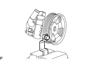
1. FIX VANE PUMP ASSEMBLY
|
(a) Using SST, fix the vane pump assembly in a vise. SST: 09630-00014 09631-00132 NOTICE: When using a vise, do not overtighten it. |
|
2. REMOVE POWER STEERING SUCTION PORT UNION
|
(a) Remove the bolt and suction port union. |
|
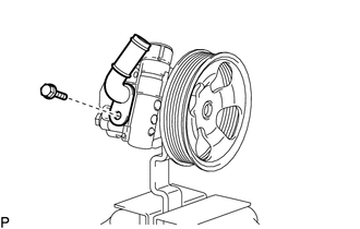
(b) Remove the O-ring from the suction port union.
3. REMOVE FLOW CONTROL VALVE ASSEMBLY
|
(a) Remove the pressure port union. |
|
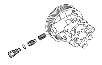
(b) Remove the O-ring from the pressure port union.
(c) Remove the flow control valve assembly and compression spring.
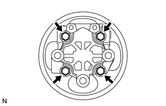
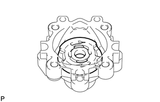
4. REMOVE REAR VANE PUMP HOUSING
|
(a) Remove the 4 bolts and rear vane pump housing from the front vane pump housing. |
|
|
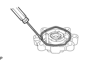
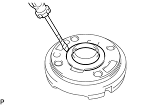
(b) Using a screwdriver, remove the O-ring from the rear vane pump housing. |
|
5. REMOVE PULLEY SHAFT SUB-ASSEMBLY
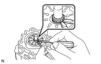
(a) Using a screwdriver, remove the snap ring from the pulley shaft sub-assembly.
|
(b) Remove the pulley shaft. NOTICE: Be careful not to drop or damage the pulley shaft. If damaged, replace it with a new one. |
|
6. REMOVE VANE PUMP ROTOR
|
(a) Remove the 10 vane pump plates. NOTICE: Take care not to drop the vane pump plates. |
|
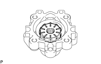
(b) Remove the vane pump rotor from the front vane pump housing.
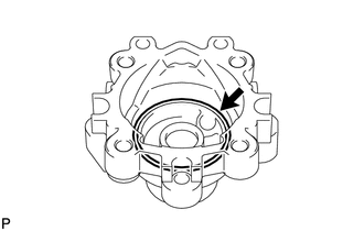
7. REMOVE VANE PUMP CAM RING
|
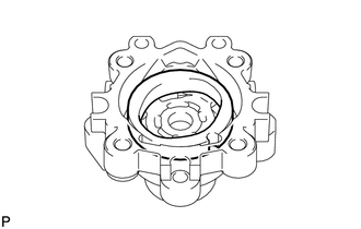
(a) Remove the vane pump cam ring from the front vane pump housing. |
|
8. REMOVE FRONT VANE PUMP SIDE PLATE
|
(a) Remove the front vane pump side plate from the front vane pump housing. |
|
|
(b) Using a screwdriver, remove the O-ring from the front vane pump side plate. |
|
|
(c) Remove the O-ring from the front vane pump housing. |
|
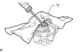
9. REMOVE VANE PUMP HOUSING OIL SEAL
|
(a) Using screwdriver, remove the vane pump housing oil seal. Text in Illustration
NOTICE: Be careful not to damage the front vane pump housing. |
|
 Components
COMPONENTS
ILLUSTRATION
ILLUSTRATION
...
 Removal
REMOVAL
PROCEDURE
1. REMOVE NO. 2 ENGINE UNDER COVER SUB-ASSEMBLY (w/ Off Road Package)
2. REMOVE NO. 1 ENGINE UNDER COVER SUB-ASSEMBLY
3. REMOVE FAN AND GENERATOR V BELT
4. DRAIN POWER STEERI ...
Other materials:
Installation of a mobile two-way radio system
The installation of a mobile two-way radio system in your vehicle could affect
electronic systems such as: ● Multiport fuel injection system/sequential multiport
fuel injection system
● Cruise control system
● Anti-lock brake system
● SRS airbag system
● Seat be ...
Vehicle Speed Tolerance Malfunction (C1AA2)
DESCRIPTION
The forward recognition camera receives vehicle speed tolerance signals from
the combination meter assembly. If the combination meter assembly detects a vehicle
speed tolerance malfunction signal, it informs the forward recognition camera via
CAN communication, and DTC C1AA2 is st ...
Data List / Active Test
DATA LIST / ACTIVE TEST
1. DATA LIST
HINT:
Using the Techstream to read the Data List allows the values or states of switches,
sensors, actuators and other items to be read without removing any parts. This non-intrusive
inspection can be very useful because intermittent conditions or signals ...
