Toyota Tacoma (2015-2018) Service Manual: System Diagram
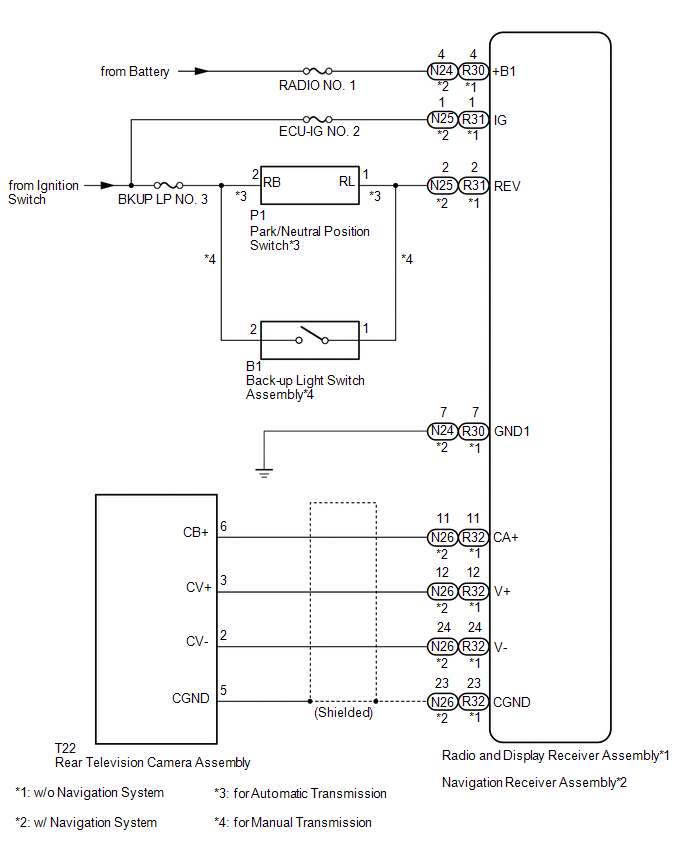
SYSTEM DIAGRAM
 Parts Location
PARTS LOCATION
ILLUSTRATION
ILLUSTRATION
...
 How To Proceed With Troubleshooting
CAUTION / NOTICE / HINT
HINT:
Use these procedures to troubleshoot the rear view monitor system.
PROCEDURE
1.
VEHICLE BROUGHT TO WORKSHOP
NEX ...
Other materials:
Destination Information Undefined (C1AB8)
DESCRIPTION
This DTC is stored when correct destination information is not sent from the
main body ECU (multiplex network body ECU) and destination information cannot be
confirmed after a blind spot monitor has been replaced.
DTC Code
DTC Detection Condition
Tr ...
Dtc Check / Clear
DTC CHECK / CLEAR
1. CHECK DTC (CHECK USING TECHSTREAM)
(a) Connect the Techstream to the DLC3.
(b) Turn the ignition switch to ON.
(c) Turn the Techstream on.
(d) Enter the following menus: Body Electrical / Navigation System / Trouble
Codes.
(e) Check for DTCs, and then write them down.
( ...
Removal
REMOVAL
PROCEDURE
1. REMOVE FRONT CONSOLE BOX
(See page )
2. DISCONNECT TRANSMISSION CONTROL CABLE ASSEMBLY
3. REMOVE TRANSMISSION CONTROL CABLE ASSEMBLY
(a) Remove the nut and clip and disconnect the transmission control cable
assembly from the automatic transmission assem ...
