Toyota Tacoma (2015-2018) Service Manual: System Diagram
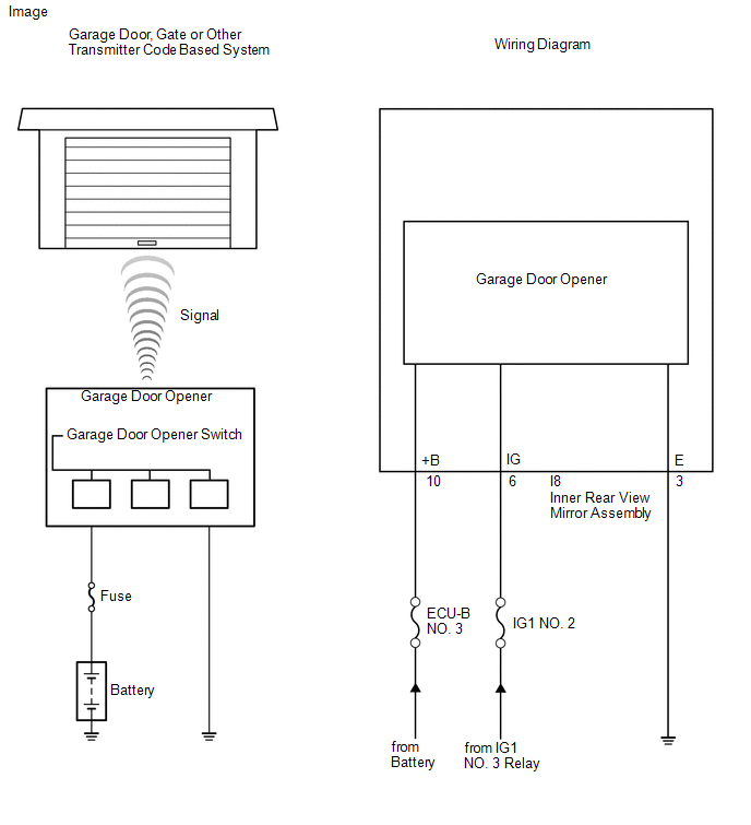
SYSTEM DIAGRAM
 Parts Location
PARTS LOCATION
ILLUSTRATION
...
 System Description
SYSTEM DESCRIPTION
1. DESCRIPTION
(a) A maximum of 3 kinds of transmitter code based systems (example: garage doors,
gates and entry gates) can be registered with the vehicle's garage door ope ...
Other materials:
Compressor Lock Sensor Circuit (B1422/22)
SYSTEM DESCRIPTION
The ECM sends the engine speed signal to the air conditioning amplifier assembly
via CAN communication.
The air conditioning amplifier assembly reads the difference between compressor
speed and engine speed. When the difference becomes too large, the air conditioning
ampli ...
Check Mode Procedure
CHECK MODE PROCEDURE
1. DESCRIPTION
(a) Check mode has a higher sensitivity to malfunctions and can detect malfunctions
that normal mode cannot detect. Check mode can also detect all the malfunctions
that normal mode can detect. In check mode, DTCs are detected with 1 trip detection
logic.
...
Winter driving tips
Carry out the necessary preparations and inspections before driving the vehicle
in winter. Always drive the vehicle in a manner appropriate to the prevailing weather
conditions.
■ Pre-winter preparations
● Use fluids that are appropriate to the prevailing outside temperatures.
ÔÇó ...
