Toyota Tacoma (2015-2018) Service Manual: Parts Location
PARTS LOCATION
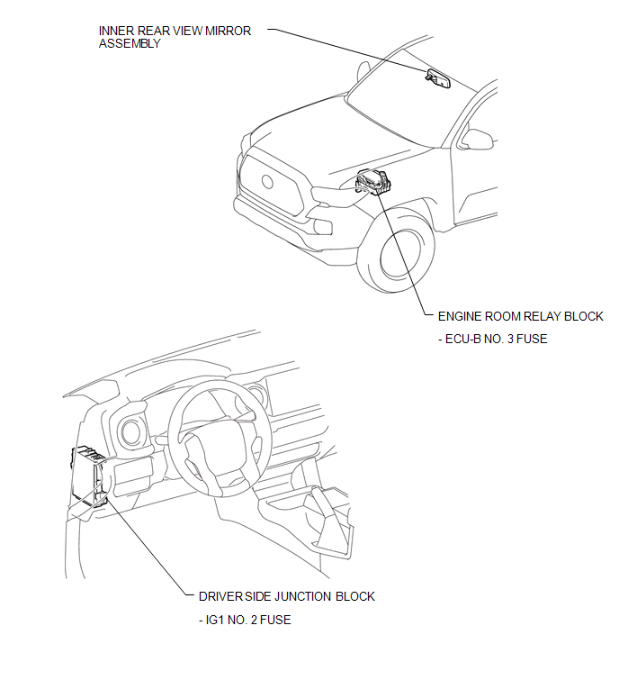
ILLUSTRATION

 System Diagram
SYSTEM DIAGRAM
...
Other materials:
On-vehicle Inspection
ON-VEHICLE INSPECTION
PROCEDURE
1. INSPECT ENGINE COOLANT
(See page )
2. INSPECT ENGINE OIL
(See page )
3. INSPECT BATTERY
(See page )
4. INSPECT SPARK PLUG
(See page )
5. INSPECT AIR CLEANER FILTER ELEMENT SUB-ASSEMBLY
(a) Remove the air cleaner filter element sub-assembly.
(b) Visu ...
Installation
INSTALLATION
PROCEDURE
1. INSTALL WINDSHIELD WIPER MOTOR ASSEMBLY
(a) Apply MP grease to the crank arm pivot of the windshield wiper motor
assembly.
Text in Illustration
*1
Crank Arm Pivot
...
Accumulator Low Pressure (C1452)
DESCRIPTION
DTC Code
DTC Detection Condition
Trouble Area
C1452
After braking, the fluid pressure inside the accumulator is below the
threshold within 3.2 seconds.
Hydraulic circuit
Accumulator pressure sen ...
