Toyota Tacoma (2015-2018) Service Manual: System Diagram
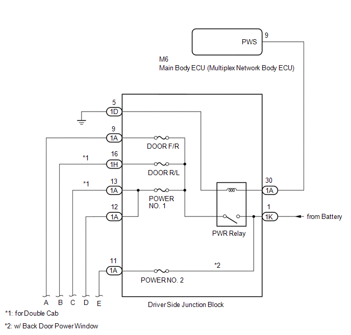
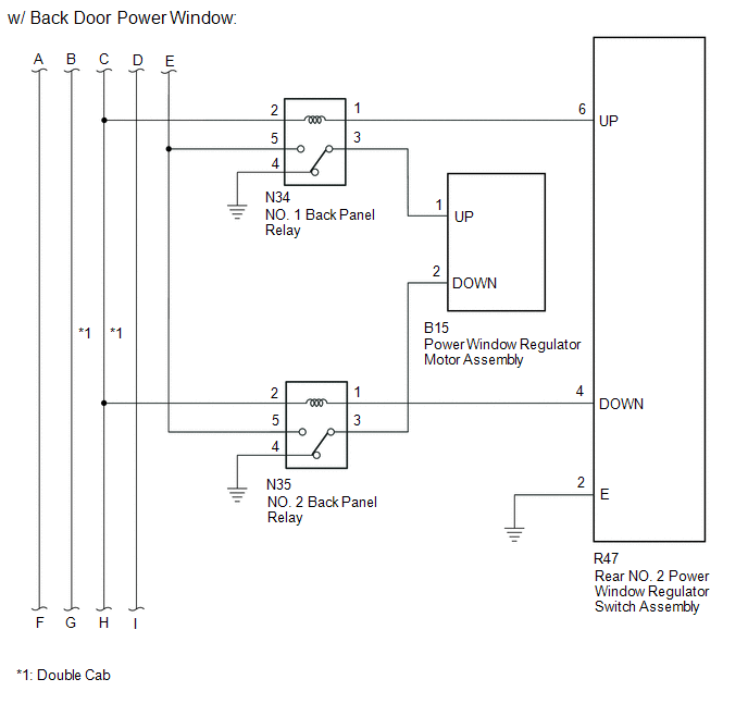
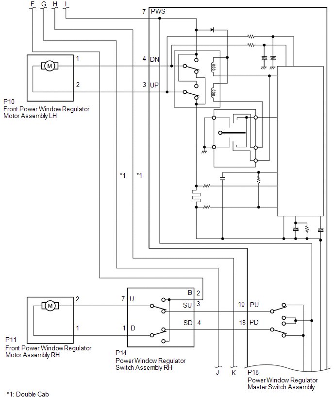
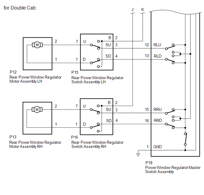
SYSTEM DIAGRAM
 System Description
SYSTEM DESCRIPTION
1. POWER WINDOW CONTROL SYSTEM DESCRIPTION
(a) The power window control system controls the power window operation using
the power window regulator motors. The main controls of ...
 Operation Check
OPERATION CHECK
1. CHECK WINDOW LOCK FUNCTION
(a) Turn the ignition switch ON.
(b) Press the window lock switch of the power window regulator master switch
assembly.
HINT:
The illumination (LED ...
Other materials:
Front passenger occupant classification system
Your vehicle is equipped with a front passenger occupant classification system.
This system detects the conditions of the right front passenger seat and activates
or deactivates the devices for the front passenger.
1. SRS warning light
2. Front passenger’s seat belt reminder light
3. AIR ...
Diagnostic Trouble Code Chart
DIAGNOSTIC TROUBLE CODE CHART
Intuitive Parking Assist System
DTC Code
Detection Item
See page
C1AE6
Rear Left Sensor Malfunction
C1AE7
Rear Left Center Sensor Malfunction
...
Removal
REMOVAL
PROCEDURE
1. PRECAUTION
NOTICE:
After turning the ignition switch off, waiting time may be required before disconnecting
the cable from the negative (-) battery terminal. Therefore, make sure to read the
disconnecting the cable from the negative (-) battery terminal notices before pr ...
