Toyota Tacoma (2015-2018) Service Manual: Disassembly
DISASSEMBLY
PROCEDURE
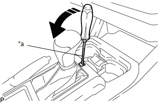
1. REMOVE SHIFT LOCK RELEASE BUTTON COVER
(a) Using a screwdriver with its tip wrapped in protective tape, detach the 2 claws to remove the shift lock release button cover from the console upper panel sub-assembly.
 Text in Illustration
|
*a |
Protective Tape |
 |
Remove in this Direction |
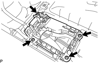
2. REMOVE SHIFT POSITION INDICATOR
|
(a) Remove the 4 screws and shift position indicator from the console upper panel sub-assembly. |
|
3. REMOVE INDICATOR LIGHT WIRE SUB-ASSEMBLY
|
(a) Detach the clamp to separate the indicator light wire sub-assembly from the shift position indicator. |
|
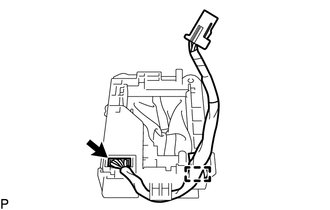
(b) Disconnect the connector to remove the indicator light wire sub-assembly from the shift position indicator.
 Components
COMPONENTS
ILLUSTRATION
...
 On-vehicle Inspection
ON-VEHICLE INSPECTION
PROCEDURE
1. INSPECT SHIFT LEVER POSITION
(a) When moving the shift lever from P to each position with the ignition switch
ON and the brake pedal depressed, check that the s ...
Other materials:
Dtc Check / Clear
DTC CHECK / CLEAR
1. CHECK DTC (for TIRE PRESSURE WARNING ECU AND RECEIVER) (USING TECHSTREAM)
(a) Turn the ignition switch off.
(b) Connect the Techstream to the DLC3.
(c) Turn the ignition switch to ON.
(d) Turn the Techstream on.
(e) Enter the following menus: Chassis / Tire Pressure Monito ...
Inspection
INSPECTION
PROCEDURE
1. INSPECT FRONT NO. 2 SPEAKER ASSEMBLY
(a) When there is a malfunction such as noise from a speaker or no sound at all,
replace the speaker with a new one and check that the malfunction disappears.
OK:
Malfunction disappears.
HINT:
Connect the connectors to th ...
Vehicle Speed Tolerance Malfunction (C1AA2)
DESCRIPTION
The forward recognition camera receives vehicle speed tolerance signals from
the combination meter assembly. If the combination meter assembly detects a vehicle
speed tolerance malfunction signal, it informs the forward recognition camera via
CAN communication, and DTC C1AA2 is st ...
