Toyota Tacoma (2015-2018) Service Manual: System Diagram
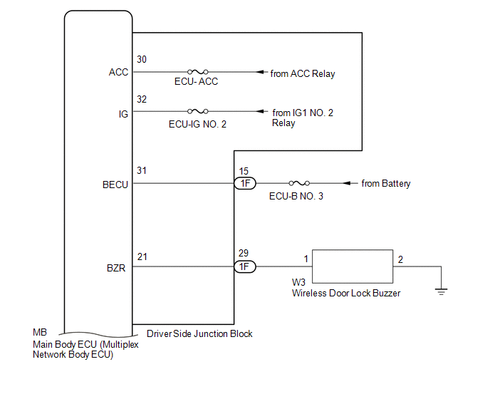
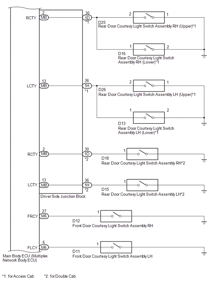
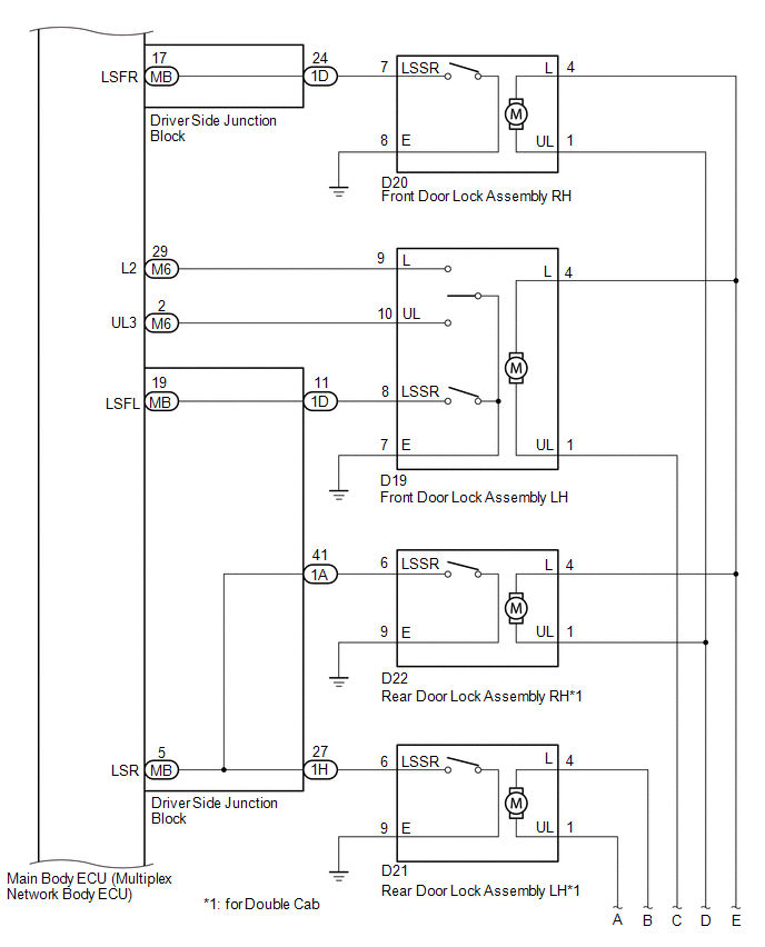
SYSTEM DIAGRAM
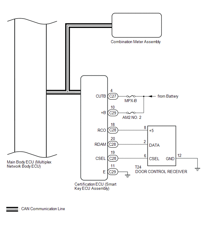
 Communication Table
|
Transmitting ECU (Transmitter) |
Receiving ECU (Receiver) |
Signal |
Line |
|---|---|---|---|
|
Certification ECU (Smart Key ECU Assembly) |
Main Body ECU (Multiplex Network Body ECU) |
|
CAN |
|
Main Body ECU (Multiplex Network Body ECU) |
Combination Meter Assembly |
Wireless door lock hazard warning light request signal |
CAN |
 System Description
SYSTEM DESCRIPTION
1. WIRELESS DOOR LOCK CONTROL SYSTEM
The wireless door lock control system can be used to lock and unlock all doors
from a distance. The system is controlled by an electrical ke ...
 Customize Parameters
CUSTOMIZE PARAMETERS
PROCEDURE
1. CUSTOMIZE WIRELESS DOOR LOCK CONTROL SYSTEM (w/ Smart Key System)
HINT:
The following items can be customized.
NOTICE:
When the customer requests a chan ...
Other materials:
Data List / Active Test
DATA LIST / ACTIVE TEST
NOTICE:
In the table below, the values listed under "Normal Condition" are reference
values. Do not depend solely on these reference values when deciding whether a part
is faulty or not.
HINT:
Using the Techstream to read the Data List allows the values or s ...
Power windows*
The power windows can be opened/closed using the following switches.
Driver’s power window switches
Closing
Opening
One-touch opening (driver’s window
only)*
*: To stop the window partway, operate the switch in the opposite direction.
Front and rear passenger’s power
window swi ...
ECU Power Source Circuit
DESCRIPTION
This circuit supplies power to the millimeter wave radar sensor assembly when
the ignition switch is ON.
WIRING DIAGRAM
CAUTION / NOTICE / HINT
NOTICE:
Inspect the fuses for circuits related to this system before performing the following
inspection procedure.
PROCEDURE
...
