Toyota Tacoma (2015-2018) Service Manual: System Diagram
SYSTEM DIAGRAM
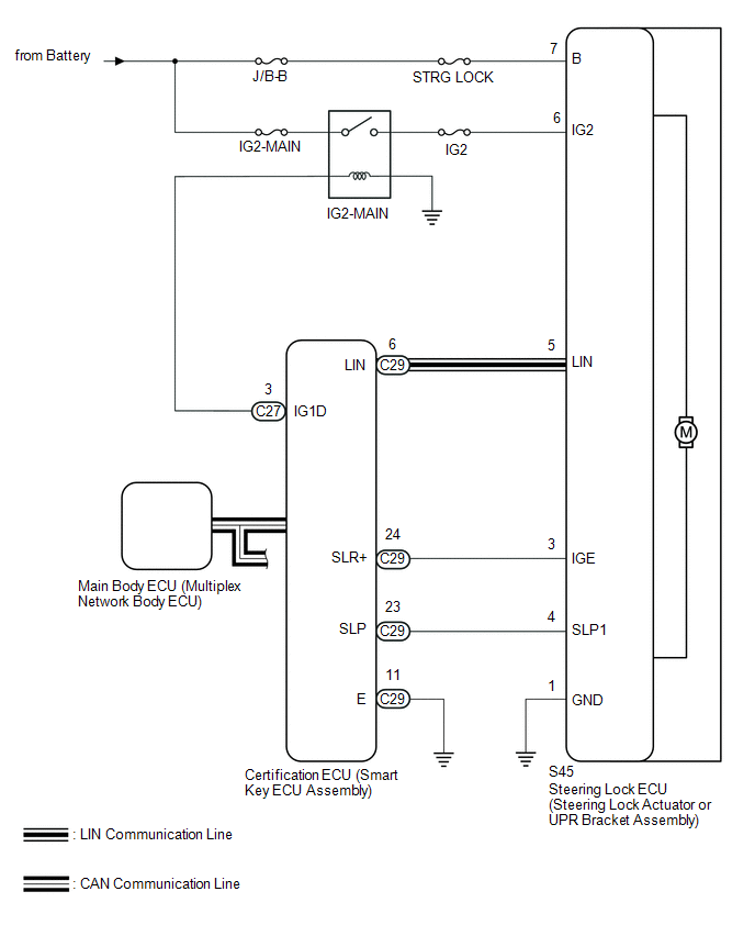 Circuit Description
|
Component |
Outline |
|---|---|
|
Steering Lock ECU (Steering Lock Actuator or UPR Bracket Assembly) |
|
|
Certification ECU (Smart Key ECU Assembly) |
|
 System Description
SYSTEM DESCRIPTION
1. UNLOCK OPERATION CONDITIONS FOR STEERING LOCK
(a) When the following condition is met, the unlock operation is performed.
The engine switch is on (ACC) or on (IG).
H ...
 How To Proceed With Troubleshooting
CAUTION / NOTICE / HINT
HINT:
Use the following procedures to troubleshoot the steering lock system.
*: Use the Techstream.
PROCEDURE
1.
VEHICLE BROUGHT ...
Other materials:
On-vehicle Inspection
ON-VEHICLE INSPECTION
CAUTION / NOTICE / HINT
HINT:
Perform "Inspection After Repair" after replacing an ignition coil assembly or
spark plug (See page ).
PROCEDURE
1. PERFORM SPARK TEST
(a) Check for DTCs (See page ).
NOTICE:
If any DTC is output, perform the troubleshooting p ...
Luggage compartment features
Behind the rear seat (Double
Cab models only)
1.Cargo net hooks (vehicles with sub woofer)
2.Grocery bag hooks
3.Flashlight holder
4.Storage boxes
Deck
1. Auxiliary boxes
2. Tie-down cleats
3. Deck hooks
Auxiliary boxes
Left side
1. Turn the knob counterclockwise.
2. Open the ...
Installation
INSTALLATION
CAUTION / NOTICE / HINT
HINT:
Use the same procedure for both the RH and LH sides.
The procedure described below is for the LH side.
PROCEDURE
1. INSTALL CURTAIN SHIELD AIRBAG ASSEMBLY
(a) Insert the 5 hooks, install 6 new bolts, 2 new clips with pins and 2 new
...
