Toyota Tacoma (2015-2018) Service Manual: Lost Communication With Image Processing Module "A" (U023A)
DESCRIPTION
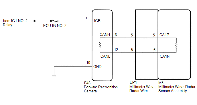
The millimeter wave radar sensor assembly communicates with the forward recognition camera via CAN communication. If there is a communication error with the forward recognition camera, the millimeter wave radar sensor assembly stores DTC U023A.
|
DTC No. |
Detection Item |
DTC Detection Condition |
Trouble Area |
|---|---|---|---|
|
U023A |
Lost Communication With Image Processing Module "A" |
When the ignition switch is ON, a communication error between the forward recognition camera and millimeter wave radar sensor assembly is detected for approximately 1 second. |
|
WIRING DIAGRAM
CAUTION / NOTICE / HINT
NOTICE:
- Inspect the fuses for circuits related to this system before performing the following inspection procedure.
- Before measuring the resistance of the CAN bus, turn the ignition switch off and leave the vehicle for 1 minute or more without operating the key or any switches, or opening or closing the doors. After that, disconnect the cable from the negative (-) battery terminal and leave the vehicle for 1 minute or more before measuring the resistance.
- After turning the ignition switch off, waiting time may be required
before disconnecting the cable from the negative (-) battery terminal. Therefore,
make sure to read the disconnecting the cable from the negative (-) battery
terminal notices before proceeding with work.
Click here
.gif)
- When replacing the forward recognition camera, always replace it with a new one. If a forward recognition camera which was installed to another vehicle is used, the information stored in the forward recognition camera will not match the information from the vehicle. As a result, a DTC may be stored.
- If the forward recognition camera has been replaced with a new one,
be sure to perform forward recognition camera adjustment.
Click here
HINT:
- Before disconnecting related connectors for inspection, push in on each connector body to check that the connector is not loose or disconnected.
- When a connector is disconnected, check that the terminals and connector body are not cracked, deformed or corroded.
PROCEDURE
|
1. |
READ VALUE USING TECHSTREAM (CAN BUS CHECK) |
(a) Connect the Techstream to the DLC3.
(b) Turn the ignition switch to ON.
(c) Turn the Techstream on.
(d) Enter the following menus: System Select / Can Bus Check.
|
Result |
Proceed to |
|---|---|
|
All of the ECUs and sensors that are currently connected to the CAN communication system are displayed |
A |
|
None of the ECUs and sensors that are currently connected to the CAN communication system are displayed, or some of them are not displayed |
B |
| B | .gif) |
GO TO CAN COMMUNICATION SYSTEM |
|
.gif)
|
2. |
CHECK FOR DTCs (PRE-COLLISION SYSTEM) |
(a) Clear the DTCs.
Click here
(b) Make sure that the DTC detection conditions are met.
HINT:
If the detection conditions are not met, the system cannot detect the malfunction.
(c) Check for DTCs.
Click here
|
Result |
Proceed to |
|---|---|
|
DTC U1002 is not output |
A |
|
DTC U1002 is output |
B |
| B | |
GO TO DTC CHART (U1002) |
|
|
3. |
CHECK FOR OPEN IN CAN BUS LINES (MILLIMETER WAVE RADAR SENSOR ASSEMBLY - FORWARD RECOGNITION CAMERA) |
(a) Disconnect the F46 forward recognition camera connector.
(b) Disconnect the M8 millimeter wave radar sensor assembly connector.
(c) Measure the resistance according to the value(s) in the table below.
Standard Resistance:
|
Tester Connection |
Condition |
Specified Condition |
|---|---|---|
|
F46-6 (CANH) - M8-5 (CA1P) |
Cable disconnected from negative (-) battery terminal |
Below 1 Ω |
|
F46-12 (CANL) - M8-6 (CA1N) |
Cable disconnected from negative (-) battery terminal |
Below 1 Ω |
(d) Connect the M8 millimeter wave radar sensor assembly connector.
(e) Connect the F46 forward recognition camera connector.
| NG | |
GO TO STEP 5 |
|
|
4. |
CHECK HARNESS AND CONNECTOR (POWER SOURCE VOLTAGE) |
|
(a) Disconnect the forward recognition camera connector. |
|
(b) Measure the resistance according to the value(s) in the table below.
Standard Resistance:
|
Tester Connection |
Condition |
Specified Condition |
|---|---|---|
|
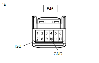
F46-10 (GND) - Body ground |
Always |
Below 1 Ω |
(c) Connect the cable to the negative (-) battery terminal.
(d) Measure the voltage according to the value(s) in the table below.
Standard Voltage:
|
Tester Connection |
Condition |
Specified Condition |
|---|---|---|
|
F46-7 (IGB) - Body ground |
Ignition switch ON |
11 to 14 V |
(e) Connect the F46 forward recognition camera connector.
| OK | |
REPLACE FORWARD RECOGNITION CAMERA |
| NG | |
REPAIR OR REPLACE HARNESS OR CONNECTOR (POWER SOURCE CIRCUIT) |
|
5. |
CHECK FOR OPEN IN CAN BUS LINES (MILLIMETER WAVE RADAR WIRE - FORWARD RECOGNITION CAMERA) |
(a) Disconnect the F46 forward recognition camera connector.
(b) Disconnect the EP1 millimeter wave radar wire connector.
(c) Measure the resistance according to the value(s) in the table below.
Standard Resistance:
|
Tester Connection |
Condition |
Specified Condition |
|---|---|---|
|
F46-6 (CANH) - EP1-5 |
Cable disconnected from negative (-) battery terminal |
Below 1 Ω |
|
F46-12 (CANL) - EP1-6 |
Cable disconnected from negative (-) battery terminal |
Below 1 Ω |
(d) Connect the F46 millimeter wave radar wire connector.
(e) Connect the EP1 forward recognition camera connector.
| OK | |
REPAIR MILLIMETER WAVE RADAR WIRE |
| NG | |
REPAIR OR REPLACE CAN BUS LINE OR CONNECTOR (MILLIMETER WAVE RADAR WIRE - FORWARD RECOGNITION CAMERA) |
 Fail-safe Chart
FAIL-SAFE CHART
FAIL-SAFE FUNCTION
(a) When a malfunction occurs in the pre-collision system, a message will be
displayed on the multi-information display and the pre-collision system will be
di ...
 Vehicle Control History
VEHICLE CONTROL HISTORY
VEHICLE CONTROL HISTORY
(a) A part of the control history can be confirmed using the vehicle control
history.
Click here ...
Other materials:
Oil Pressure Switch
Components
COMPONENTS
ILLUSTRATION
Removal
REMOVAL
PROCEDURE
1. REMOVE ENGINE OIL PRESSURE SWITCH ASSEMBLY
(a) Disengage the clamp and disconnect the engine oil pressure switch
connector.
(b) Using a 24 mm deep socket ...
Confirm Cellular Phone Functionality
PROCEDURE
1.
CHECK CUSTOMER'S CELLULAR PHONE COMPATIBILITY
(a) Check if the cellular phone is compatible (Refer to http://www.toyota.com/entune/).
Result
Result
Proceed to
Cellular phone is compatible
A
...
Steering Pad Switch
Components
COMPONENTS
ILLUSTRATION
*1
STEERING PAD SWITCH ASSEMBLY
-
-
Removal
REMOVAL
PROCEDURE
1. REMOVE STEERING PAD
(See page )
2. REMOVE STEERING PAD SWITCH ASSEMBLY
(a) Disconnect the 2 connectors.
...
