Toyota Tacoma (2015-2018) Service Manual: System Diagram
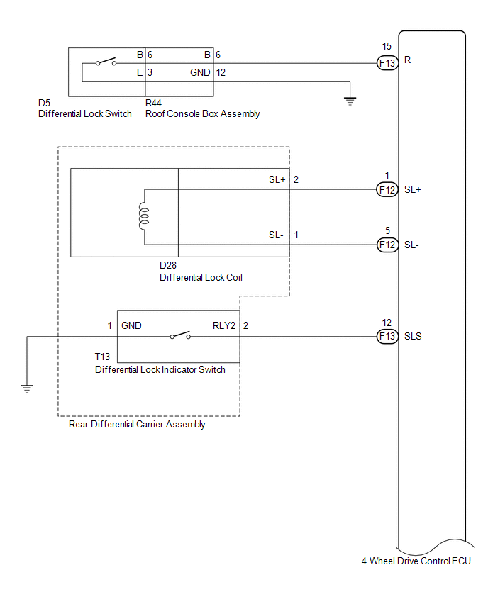
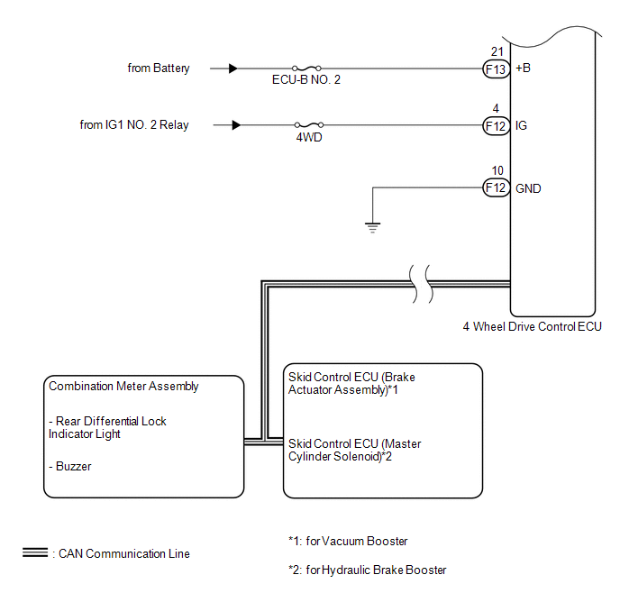
SYSTEM DIAGRAM
|
Transmitting ECU (Transmitter) |
Receiving ECU |
Signal |
Communication Method |
|---|---|---|---|
|
4 wheel drive control ECU |
Skid control ECU (Brake actuator assembly) |
|
CAN communication system |
|
Skid control ECU (Brake actuator assembly) |
4 wheel drive control ECU |
|
CAN communication system |
|
4 wheel drive control ECU |
Combination meter assembly |
|
CAN communication system |
- *: for 4WD
 Precaution
PRECAUTION
1. IGNITION SWITCH EXPRESSION
(a) The type of ignition switch used on this model differs depending on the specifications
of the vehicle. The expressions listed in the table below are us ...
 How To Proceed With Troubleshooting
CAUTION / NOTICE / HINT
HINT:
Use the following procedure listed to troubleshoot the differential
system (w/ Differential Lock).
*: Use the Techstream.
PROCEDURE
1 ...
Other materials:
Disassembly
DISASSEMBLY
PROCEDURE
1. REMOVE CONSOLE COMPARTMENT DOOR CUSHION
HINT:
Use the same procedure as for the opposite side.
(a) Disengage the claw to remove the console compartment door cushion.
2. REMOVE CONSOLE COMPARTMENT DOOR SUB-ASSEMBLY
...
SRS Warning Light does not Come ON
DESCRIPTION
See page .
WIRING DIAGRAM
See page .
CAUTION / NOTICE / HINT
NOTICE:
Inspect the fuses for circuits related to this system before performing
the following inspection procedure.
After turning the ignition switch off, waiting time may be required
before disconne ...
Precaution
PRECAUTION
1. IGNITION SWITCH EXPRESSION
HINT:
The type of ignition switch used on this model differs depending on the specifications
of the vehicle. The expressions listed in the table below are used in this section.
Expression
Ignition Switch (Position)
Engin ...
