Toyota Tacoma (2015-2018) Service Manual: System Diagram
SYSTEM DIAGRAM
 Communication Table
|
Sender |
Receiver |
Signal |
Line |
|---|---|---|---|
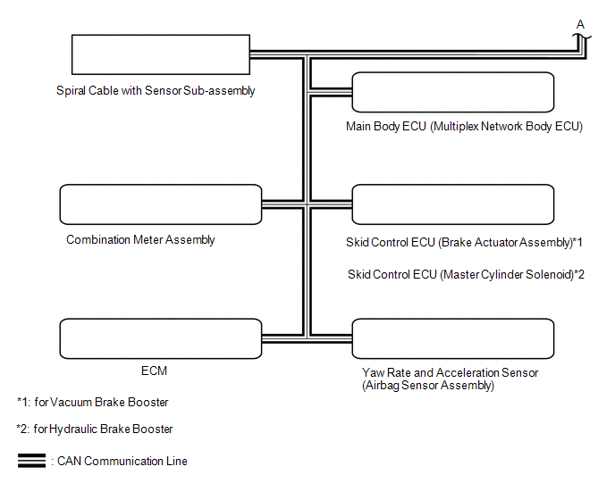
| *1: for Vacuum Brake Booster
*2: for Hydraulic Brake Booster |
|||
|
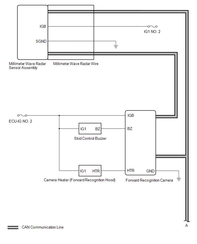
Millimeter Wave Radar Sensor Assembly |
Forward Recognition Camera |
|
CAN |
|
ECM |
Forward Recognition Camera |
|
CAN |
|
Forward Recognition Camera |
|
CAN |
|
Yaw Rate and Acceleration Sensor (Airbag Sensor Assembly) |
Forward Recognition Camera |
Vehicle yaw rate sensor signal |
CAN |
|
Main Body ECU (Multiplex Network Body ECU) |
Forward Recognition Camera |
Destination information signal |
CAN |
 System Description
SYSTEM DESCRIPTION
GENERAL DESCRIPTION
(a) The forward recognition camera processes the image captured by the monocular
camera to detect lane markers, vehicles, pedestrians, traffic signs, etc. Th ...
 How To Proceed With Troubleshooting
CAUTION / NOTICE / HINT
HINT:
Use these procedures to troubleshoot the forward recognition camera
system.
*: Use the Techstream.
PROCEDURE
1.
VEHICLE B ...
Other materials:
Does not Play even after Bluetooth Audio Mode is Selected
CAUTION / NOTICE / HINT
HINT:
Even if the portable player can play audio content, it may not be able to play
via the in-vehicle device. This does not necessarily indicate a malfunction of the
in-vehicle device.
PROCEDURE
1.
CHECK OPERATION
(a) Check if the po ...
Sliding Roof does not Move by Operating Sliding Roof Control Switch
DESCRIPTION
The sliding roof ECU (sliding roof drive gear sub-assembly) receives slide and
tilt signals when the sliding roof switch is operated and drives its built-in motor.
WIRING DIAGRAM
CAUTION / NOTICE / HINT
NOTICE:
Inspect the fuses for circuits related to this system before ...
Diagnostic Trouble Code Chart
DIAGNOSTIC TROUBLE CODE CHART
HINT:
If a trouble code is output during the DTC check, inspect the trouble areas listed
for that code. For details of the code, refer to the "See page".
DTC Code
Detection Item
See page
B1500
F ...
