Toyota Tacoma (2015-2018) Service Manual: Inspection
INSPECTION
PROCEDURE
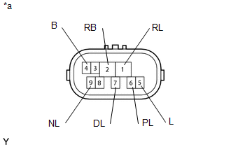
1. INSPECT PARK/NEUTRAL POSITION SWITCH
|
(a) Measure the resistance according to the value(s) in the table below. Text in Illustration
Standard Resistance:
If the resistance value is not as specified, replace the park/neutral position switch. |
|
 Adjustment
ADJUSTMENT
PROCEDURE
1. ADJUST PARK/NEUTRAL POSITION SWITCH
(a) While pushing the shift lock release button, move the shift lever to N.
(b) Remove the bolt of the park/neutral position switch.
(c ...
 Installation
INSTALLATION
PROCEDURE
1. INSTALL PARK/NEUTRAL POSITION SWITCH
HINT:
Make sure that the manual valve lever shaft has not been rotated prior to installing
the park/neutral position switch as the ...
Other materials:
Disassembly
DISASSEMBLY
PROCEDURE
1. INSPECT PROPELLER SHAFT UNIVERSAL JOINT SPIDER BEARING
(a) Check the spider bearings for wear and damage.
(b) Check each spider bearings axial play by turning the yoke while holding the
shaft tightly.
Maximum bearing axial play:
0 to 0.05 mm (0 to 0.00197 in.)
If t ...
Automatic Transmission Unit(for 2tr-fe)
Components
COMPONENTS
ILLUSTRATION
ILLUSTRATION
ILLUSTRATION
ILLUSTRATION
ILLUSTRATION
ILLUSTRATION
ILLUSTRATION
ILLUSTRATION
ILLUSTRATION
...
Fail-safe Chart
FAIL-SAFE CHART
1. Fail-safe
This function minimizes the loss of operation when any abnormality occurs in
a sensor or solenoid.
Fail-safe Control List
Malfunction Part
Function
Transmission revolution sensor (NT)
During a transmission revolutio ...
