Toyota Tacoma (2015-2018) Service Manual: System Description
SYSTEM DESCRIPTION
1. OUTLINE OF THEFT DETERRENT SYSTEM
- The theft deterrent system can be set/canceled by locking/unlocking
the doors using the following operation:
- Entry lock operation*1
- Wireless lock operation*2
- Key-linked lock operation
- *1: w/ Smart Key System
- *2: w/ Wireless Door Lock System
- The alarm function will be activated when someone attempts to forcibly unlock any of the doors or open any of the doors, engine hood while the system is in the armed state.
- In the alarm sounding state, the system illuminates the interior light
and blinks the hazard warning lights, the headlights and taillights. At
the same time, the system sounds the vehicle horns and security horn to
deter break-in and theft as well as to warn people around the vehicle.
HINT:
The interior light is illuminated if the No. 1 room light assembly switch in DOOR position and the roof console box assembly switch DOOR position.
- The theft deterrent system has the active arming mode. There are 4 states; a disarmed state, an arming preparation state, an armed state and an alarm sounding state.
(a) Disarmed state:
- The alarm function is not operating.
- The theft deterrent system is not operating.
(b) Arming preparation state:
- The time until the system goes into the armed state.
- The theft deterrent system is not operating.
(c) Armed state:
- The theft deterrent system is operating.
(d) Alarm sounding state:
- The alarm function is operating.
Alarm time:
Approximately 57 seconds
Alarm Methods and Time|
Alarm Method |
Headlights |
Blinking |
|
Taillights |
Blinking |
|
|
Hazard Warning Lights |
Blinking |
|
|
Interior Light |
Illuminating |
|
|
Vehicle Horns |
Sounding (approximately. 0.4-second cycles) |
|
|
Security Horn |
Sounding (approximately. 0.4-second cycles) |
|
|
Alarm Time |
Approximately 57 seconds |
|
2. FUNCTION OF MAIN COMPONENTS
|
Component |
Function |
|---|---|
|
Security indicator light |
Informs driver of theft deterrent system status. |
|
Security horn |
Sounds when attempted break-in or theft is detected. |
|
Headlights |
Blink when attempted break-in or theft is detected. |
|
Taillights |
|
|
Hazard warning lights |
Blink when attempted break-in or theft is detected. |
|
Interior light |
Comes on when attempted break-in or theft is detected. |
|
Vehicle horns |
Sound when attempted break-in or theft is detected. |
|
Door courtesy light switch |
Detects door status (open or closed). |
|
Door unlock detection switch |
Detects door status (locked or unlocked). |
|
Hood courtesy switch |
Detects hood status (open or closed). |
|
Certification ECU (smart key ECU assembly)*1 |
|
|
Main body ECU (multiplex network body ECU)*2 |
Receives wireless door lock/unlock signal. |
- *1: w/ Smart Key System
- *2: w/ Wireless Door Lock System
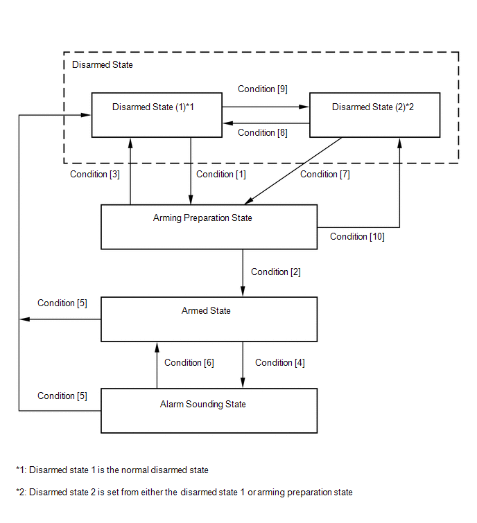
3. ACTIVE ARMING MODE
HINT:
Active arming mode starts the alarm control immediately after the doors are locked.
(a) Active arming mode:
This system operates as described in the diagram below when one of the items for each condition is met.
 w/ Smart Key System
|
Condition |
Item |
|---|---|
|
Condition [1] |
In disarmed state 1, when the ignition switch is off, the system state is switched if the following condition is met:
In disarmed state 1, when the ignition switch is off, the engine hood is closed, and all doors are locked, the system state is switched if the following condition is met:
|
|
Condition [2] |
Allow approximately 30 seconds to elapse. |
|
Condition [3] |
|
|
Condition [4] |
|
|
Condition [5] |
|
|
Condition [6] |
After approximately 57 seconds, alarm stops and system returns to armed state. |
|
Condition [7] |
The engine hood is closed |
|
Condition [8] |
|
|
Condition [9] |
In disarmed state 1, when the ignition switch is off, the system state is switched if the following condition is met:
In disarmed state 1, when the ignition switch is off, the engine hood is opened, and all doors are locked, the system state is switched if the following condition is met:
|
|
Condition [10] |
The engine hood is opened |
|
Condition |
Item |
|---|---|
|
Condition [1] |
In disarmed state 1, when the ignition switch is off, the system state is switched if the following condition is met when the key is not in the key cylinder:
In disarmed state 1, when the ignition switch is off, the engine hood is closed, and all doors are locked, the system state is switched if the following condition is met when the key is not in the key cylinder:
|
|
Condition [2] |
Allow approximately 30 seconds to elapse. |
|
Condition [3] |
|
|
Condition [4] |
|
|
Condition [5] |
|
|
Condition [6] |
|
|
Condition [7] |
With the engine hood closed |
|
Condition [8] |
|
|
Condition [9] |
In disarmed state 1, when the ignition switch is off, the system state is switched if the following condition is met when the key is not in the key cylinder:
In disarmed state 1, when the ignition switch is off, the engine hood is opened, and all doors are locked, the system state is switched if the following condition is met when the key is not in the key cylinder:
|
|
Condition [10] |
The engine hood is opened. |
- *1: w/ Wireless Door Lock System
4. FORCED DOOR LOCK CONTROL
(a) The forced door lock control prevents the vehicle from being tampered with. Immediately after a door is unlocked (armed starts), all doors are forced to lock by a forced door lock signal.
(1) If the following conditions are met, the forced door lock control is operated.
- The key is not in the key cylinder.*
- The theft deterrent system is in the armed state.
- Any door is unlocked.
- *: w/o Smart Key System
5. ALARM MEMORY FUNCTION
(a) If the alarm is set off (tampering is detected) while the theft deterrent system is armed, it will be stored by the alarm memory function. Whenever the theft deterrent system is canceled, the alarm memory function causes the taillights to light up for 2 seconds in order to inform you that the alarm has been set off.
(1) Conditions that cause the taillights to light up for 2 seconds:
The theft deterrent system has entered the alarm sounding state (tampering has been detected) at least once.
HINT:
Active arming mode: See Active Arming Mode.
6. PANIC ALARM CONTROL (w/ PANIC Switch)
HINT:
Security horn does not sound when the panic alarm control is operated.
(a) The panic alarm control makes it possible to voluntarily set off the panic alarm by pressing the panic switch on the wireless transmitter.
(1) Conditions that cause the panic alarm control to set off the panic alarm:
The panic switch on the wireless transmitter is pressed under the following conditions:
- The ignition switch is off.
- The theft deterrent system is not in the alarm sounding state.
(2) Conditions that cause the panic alarm control to shut off the alarm:
Any of the following conditions is met during panic alarm operation:
- The ignition switch is turned to ON.
- The panic switch is pressed again.
- Any of the switches on the wireless transmitter (lock/unlock) is pressed.
- The panic alarm ends (approximately 57 seconds have elapsed).
- The theft deterrent system switches to the alarm sounding state. Under this condition, the theft deterrent system is controlling the alarm rather than the panic alarm control. In order to cancel this alarm, refer to the theft deterrent system alarm sounding state cancellation procedure.
7. SECURITY INDICATOR LIGHT OUTPUT
(a) According to the state of the theft deterrent system, the main body ECU (multiplex network body ECU) outputs a signal to turn the security indicator light on. However, some of the actual lighting conditions of the security indicator light are different from the output signals of the main body ECU (multiplex network body ECU).
Output|
State of Theft Deterrent System |
Security Indicator Light |
|
|---|---|---|
|
Output Signal from Main Body ECU (Multiplex Network Body ECU) |
Actual Lighting Condition |
|
|
Disarmed state (1), (2) |
OFF |
OFF (Engine immobiliser system unset) BLINKING (Engine immobiliser system set) |
|
Arming preparation state |
ON |
ON |
|
Armed state |
OFF |
BLINKING |
|
Alarm sounding state |
ON |
ON |
|
Time |
Security Indicator Light |
|---|---|
|
0.125 seconds |
ON |
|
1.875 seconds |
OFF |
HINT:
When the engine immobiliser system is set, the security indicator light blinks during both the disarmed state and the armed state, due to output signals from the engine immobiliser system.
 How To Proceed With Troubleshooting
CAUTION / NOTICE / HINT
HINT:
Use this procedure to troubleshoot the theft deterrent system.
*: Use the Techstream.
PROCEDURE
1.
VEHICLE BROUGHT TO WORKSHO ...
 System Diagram
SYSTEM DIAGRAM
...
Other materials:
Pressure Control Solenoid "C" Actuator Stuck Off (P07957F)
SYSTEM DESCRIPTION
The ECM uses the vehicle speed signal and signals from the transmission revolution
sensors (NT, SP2) to detect the actual gear (1st, 2nd, 3rd, 4th, 5th or 6th gear).
The ECM compares the actual gear with the shift schedule in the ECM memory to
detect mechanical problems of t ...
Diagnosis System
DIAGNOSIS SYSTEM
1. DESCRIPTION
(a) The certification ECU (smart key ECU assembly) and ECM control the vehicle
engine immobiliser system functions. Engine immobiliser system data and Diagnostic
Trouble Codes (DTCs) can be read through the vehicle Data Link Connector 3 (DLC3).
In some cases, a ...
Inspection
INSPECTION
PROCEDURE
1. INSPECT COUNTER GEAR
(a) Using a dial indicator and 2 V-blocks, measure the counter gear runout.
Maximum runout:
0.03 mm (0.00118 in.)
If the runout is more than the maximum, replace the counter gear.
HINT:
Measure the 3 areas shown in the illust ...
