Toyota Tacoma (2015-2018) Service Manual: AUTO LSD Indicator Light does not Come ON
DESCRIPTION
The AUTO LSD does not operate even if the VSC OFF switch is pressed under the following conditions:
- The brake system is faulty.
- The temperature inside the hydraulic brake booster increases and the AUTO LSD operation is suspended.
WIRING DIAGRAM
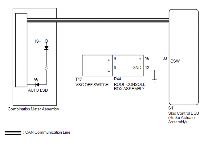
CAUTION / NOTICE / HINT
NOTICE:
When replacing the brake actuator assembly, perform calibration (See page
.gif) ).
).
PROCEDURE
|
1. |
CHECK CAN COMMUNICATION LINE |
(a) Turn the ignition switch off.
(b) Connect the Techstream to the DLC3.
(c) Turn the ignition switch to ON.
(d) Turn the Techstream on.
(e) Select CAN Bus Check from the System Selection Menu screen and follow the
prompts on the screen to inspect the CAN bus (See page
).
OK:
CAN Bus Check indicates no malfunctions in CAN communication.
| NG | .gif) |
GO TO CAN COMMUNICATION SYSTEM (HOW TO PROCEED WITH TROUBLESHOOTING) |
|
.gif)
|
2. |
INSPECT VSC OFF SWITCH |
(a) Turn the ignition switch off.
(b) Remove the VSC OFF switch (See page ).
(c) Inspect the VSC OFF switch (See page ).
OK:
The VSC OFF switch operates normally.
| NG | |
REPLACE VSC OFF SWITCH |
|
|
3. |
CHECK HARNESS AND CONNECTOR (BRAKE ACTUATOR ASSEMBLY - VSC OFF SWITCH) |
(a) Disconnect the S1 skid control ECU (brake actuator assembly) connector.
(b) Measure the resistance according to the value(s) in the table below.
Standard Resistance:
|
Tester Connection |
Condition |
Specified Condition |
|---|---|---|
|
S1-33 (CSW) - R44-16 |
Always |
Below 1 Ω |
|
S1-33 (CSW) or R44-16 -Body ground |
Always |
10 kΩ or higher |
|
R44-12 - Body ground |
Always |
Below 1 Ω |
| NG | |
REPAIR OR REPLACE HARNESS OR CONNECTOR |
|
|
4. |
READ VALUE USING TECHSTREAM (AUTO LSD INDICATOR LIGHT) |
(a) Turn the ignition switch off.
(b) Connect the Techstream to the DLC3.
(c) Turn the ignition switch to ON.
(d) Turn the Techstream on.
(e) Enter the following menus: Chassis / ABS/VSC/TRAC / Data List.
ABS/VSC/TRAC|
Tester Display |
Measurement Item/Range |
Normal Condition |
Diagnostic Note |
|---|---|---|---|
|
Auto LSD Indicator Light |
Auto LSD indicator light/ ON or OFF |
ON: Indicator light on OFF: Indicator light off |
- |
(f) When performing the Auto LSD Indicator Light Active Test, check Auto LSD
Indicator Light in the Data List (See page
).
|
Tester Display |
Test Part |
Control Range |
Diagnostic Note |
|---|---|---|---|
|
Auto LSD Indicator Light |
Auto LSD indicator light |
Indicator light ON/OFF |
Observe the combination meter. |
|
Result |
Proceed to |
|
|---|---|---|
|
Data List Display |
Data List Display when Performing Active Test ON/OFF Operation |
|
|
ON |
Does not change between ON and OFF |
A |
|
Changes between ON and OFF |
B |
|
|
OFF |
Does not change between ON and OFF |
A |
|
Changes between ON and OFF |
B |
|
| A | |
REPLACE MASTER CYLINDER SOLENOID |
| B | |
GO TO METER / GAUGE SYSTEM (HOW TO PROCEED WITH TROUBLESHOOTING) |
 Slip Indicator Light Remains ON
DESCRIPTION
The skid control ECU (brake actuator assembly) is connected to the combination
meter assembly via CAN communication.
The slip indicator light blinks during VSC and/or TRAC operation.
...
 AUTO LSD Indicator Light Remains ON
DESCRIPTION
During normal mode, pressing the VSC OFF switch for a short amount of time changes
vehicle to AUTO LSD mode.
WIRING DIAGRAM
CAUTION / NOTICE / HINT
NOTICE:
When replacing the brak ...
Other materials:
FCM Destination Information Unmatched (C1AA1)
DESCRIPTION
When the forward recognition camera is replaced with a new one, the new forward
recognition camera attempts to store country specification information received
from the main body ECU (multiplex network body ECU) and ECM. If the country specification
information stored in the forwa ...
Open or Short in Rear Speed Sensor RH Circuit (C1407,C1408)
DESCRIPTION
Refer to DTCs C1403 and C1404 (See page ).
DTC No.
Detection Item
DTC Detection Condition
Trouble Area
C1407
Open or Short in Rear Speed Sensor RH Circuit
Either of the following is detected:
...
Installation
INSTALLATION
PROCEDURE
1. INSTALL DIFFERENTIAL SIDE GEAR SHAFT OIL SEAL
(a) Using SST and a hammer, install a new oil seal.
SST: 09554-30011
(b) Coat the oil seal lip with MP grease.
2. INSTALL FRONT DRIVE SHAFT ASSEMBLY LH
Click here
3. INSTALL FRONT DRIVE SHAFT ASSEMBLY RH
HINT:
Use ...
