Components
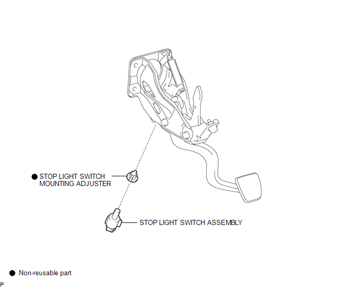
COMPONENTS
ILLUSTRATION
Inspection
INSPECTION
PROCEDURE
1. INSPECT STOP LIGHT SWITCH
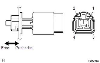
(a) Check the resistance.
(1) Measure the resistance using an ohmmeter, and check the results in accordance with the value(s) in the table below.
Standard:
|
Tester Connection |
Condition |
Specified Condition |
|---|---|---|
|
1-2 |
Switch pin free |
Below 1 Ω |
|
3-4 |
Switch pin free |
10 kΩ or higher |
|
1-2 |
Switch pin pushed in |
10 kΩ or higher |
|
3-4 |
Switch pin pushed in |
Below 1 Ω |
If the result is not as specified, replace the stop light switch assembly.
Installation
INSTALLATION
PROCEDURE
1. INSTALL STOP LIGHT SWITCH MOUNTING ADJUSTER
|
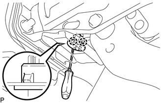
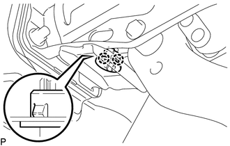
(a) Engage the 2 claws to install a new stop light switch mounting adjuster. |
|
2. INSTALL STOP LIGHT SWITCH ASSEMBLY
|
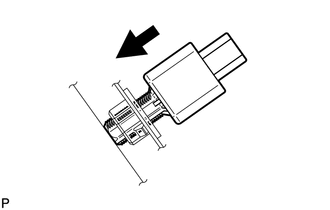
(a) Insert the stop light switch assembly to the stop light switch mounting adjuster until the switch body slightly touches the brake pedal. NOTICE: Do not depress the brake pedal. |
|
|
(b) Rotate the stop light switch assembly clockwise by approximately one fourth of a rotation. Text in Illustration
|
|
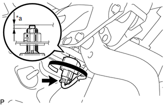
(c) Check the protrusion amount of the shaft.
Standard:
1.5 to 2.6 mm (0.0591 to 0.1024 in.)
(d) Connect the connector.
3. INSTALL LOWER NO. 1 INSTRUMENT PANEL AIRBAG ASSEMBLY
(See page .gif) )
)
Removal
REMOVAL
PROCEDURE
1. REMOVE LOWER NO. 1 INSTRUMENT PANEL AIRBAG ASSEMBLY
(See page .gif) )
)
2. REMOVE STOP LIGHT SWITCH ASSEMBLY
|
(a) Disconnect the connector. |
|
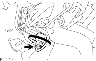
(b) Turn the stop light switch assembly counterclockwise to remove it.
3. REMOVE STOP LIGHT SWITCH MOUNTING ADJUSTER
|
(a) Using a screwdriver, disengage 2 claws to remove the stop light switch mounting adjuster. NOTICE: The stop light switch mounting adjuster must not be reused. |
|