Components
COMPONENTS
ILLUSTRATION
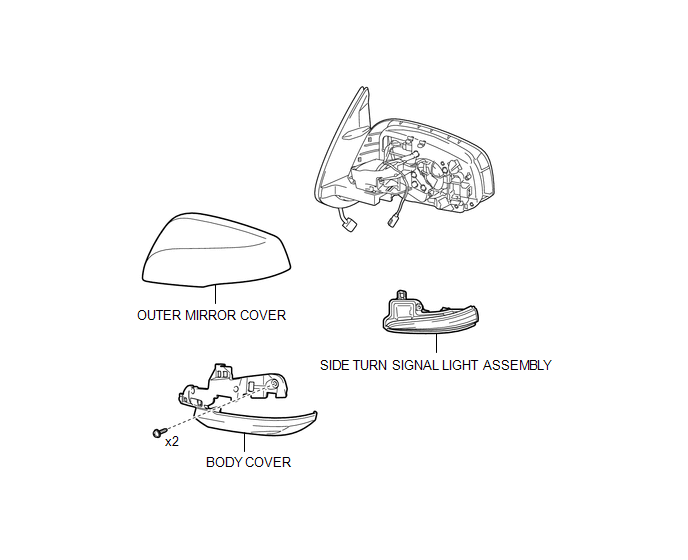
Removal
REMOVAL
CAUTION / NOTICE / HINT
HINT:
- Use the same procedure for both the RH and LH sides.
- The procedure described below is for the LH side.
PROCEDURE
1. REMOVE OUTER REAR VIEW MIRROR ASSEMBLY
(See page .gif) )
)
2. REMOVE OUTER MIRROR COVER
3. REMOVE SIDE TURN SIGNAL LIGHT ASSEMBLY
|
(a) Remove the 2 screws. |
|
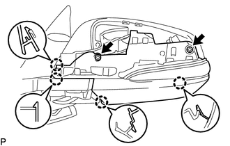
(b) Disengage the 4 claws to separate the body cover with side turn signal light assembly.
|
(c) Disengage the guide to separate the wire harness. |
|
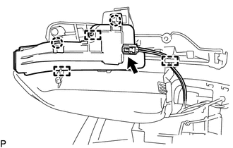
(d) Disconnect the connector to remove the body cover with side turn signal light assembly.
(e) Disengage the 2 claws and 2 guides to remove the side turn signal light assembly.
Inspection
INSPECTION
PROCEDURE
1. INSPECT SIDE TURN SIGNAL LIGHT ASSEMBLY LH
(a) Check the illuminates.
|
(1) Apply battery voltage to the connector and check the light illumination condition. Text in Illustration
OK:
If the result is not as specified, replace the side turn signal light assembly LH. |
|
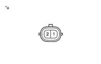
2. INSPECT SIDE TURN SIGNAL LIGHT ASSEMBLY RH
(a) Check the illuminates.
|
(1) Apply battery voltage to the connector and check the light illumination condition. Text in Illustration
OK:
If the result is not as specified, replace the side turn signal light assembly RH. |
|
Installation
INSTALLATION
CAUTION / NOTICE / HINT
HINT:
- Use the same procedure for both the LH and RH sides.
- The procedure described below is for the LH side.
PROCEDURE
1. INSTALL SIDE TURN SIGNAL LIGHT ASSEMBLY
(a) Engage the 2 guides and 2 claws to install the side turn signal light assembly.
(b) Connect the connector.
(c) Engage the clamp to install the wire harness.
(d) Engage the 4 claws to install the body cover with side turn signal light assembly.
(e) Install the 2 screws.
2. INSTALL OUTER MIRROR COVER
.gif)
3. INSTALL OUTER REAR VIEW MIRROR ASSEMBLY
(See page )