Toyota Tacoma (2015-2018) Service Manual: Steering Pad Switch Circuit
DESCRIPTION
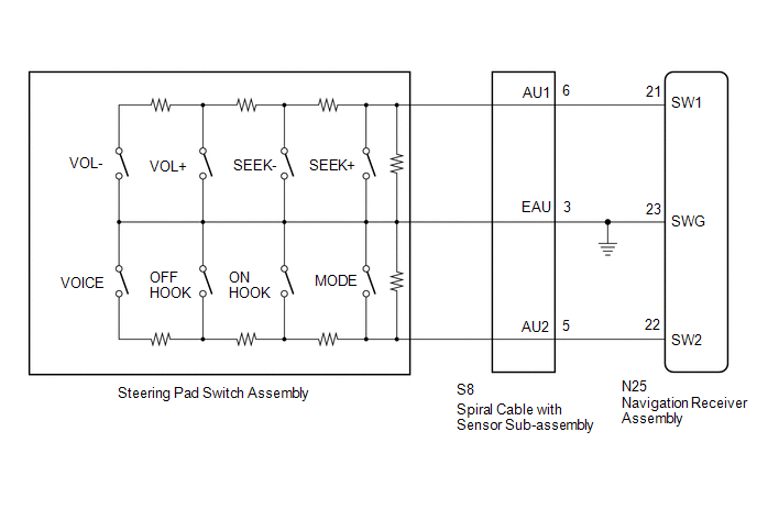
This circuit sends an operation signal from the steering pad switch assembly to the navigation receiver assembly.
If there is an open in the circuit, the audio system cannot be operated using the steering pad switch assembly.
If there is a short in the circuit, the same condition as when a switch is continuously depressed occurs.
Therefore, the navigation receiver assembly cannot be operated using the steering pad switch assembly, and also the navigation receiver assembly itself cannot function.
WIRING DIAGRAM
CAUTION / NOTICE / HINT
NOTICE:
The vehicle is equipped with a Supplemental Restraint System (SRS) which includes
components such as airbags. Before servicing (including removal or installation
of parts), be sure to read the precautionary notice for the Supplemental Restraint
System (See page .gif) ).
).
PROCEDURE
|
1. |
CHECK HARNESS AND CONNECTOR (STEERING PAD SWITCH SIGNAL) |
|
(a) Disconnect the navigation receiver assembly connector. |
|
(b) Measure the resistance according to the value(s) in the table below.
Standard Resistance:
|
Tester Connection |
Switch Condition |
Specified Condition |
|---|---|---|
|
N25-21 (SW1) - N25-23 (SWG) |
No switch is pushed |
99 to 101 kΩ |
|
Volume+ is pushed |
1000 to 1020 Ω |
|
|
Volume- is pushed |
3178 to 3242 Ω |
|
|
Seek+ is pushed |
Below 2.5 Ω |
|
|
Seek- is pushed |
327 to 333 Ω |
|
|
N25-22 (SW2) - N25-23 (SWG) |
No switch is pushed |
99 to 101 kΩ |
|
MODE switch is pushed |
Below 2.5 Ω |
|
|
On Hook switch is pushed |
327 to 333 Ω |
|
|
Off Hook switch is pushed |
1000 to 1020 Ω |
|
|
Voice switch is pushed |
3178 to 3242 Ω |
|
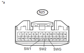
*a |
Front view of wire harness connector (to Navigation Receiver Assembly) |
| OK | .gif) |
PROCEED TO NEXT SUSPECTED AREA SHOWN IN PROBLEM SYMPTOMS TABLE |
|
.gif)
|
2. |
INSPECT STEERING PAD SWITCH ASSEMBLY |
(a) Remove the steering pad switch assembly (See page
).
(b) Inspect the steering pad switch assembly (See page
).
| NG | |
REPLACE STEERING PAD SWITCH ASSEMBLY |
|
|
3. |
INSPECT SPIRAL CABLE WITH SENSOR SUB-ASSEMBLY |
(a) Remove the spiral cable with sensor sub-assembly (See page
).
(b) Inspect the spiral cable with sensor sub-assembly (See page
).
| OK | |
REPAIR OR REPLACE HARNESS OR CONNECTOR (NAVIGATION RECEIVER ASSEMBLY - SPIRAL CABLE WITH SENSOR SUB-ASSEMBLY) |
| NG | |
REPLACE SPIRAL CABLE WITH SENSOR SUB-ASSEMBLY |
 Black Screen
PROCEDURE
1.
CHECK DISPLAY SETTING
(a) Check that the display is not in "Screen Off" mode.
OK:
The display setting is not in "Screen Off" mode. ...
 Vehicle Speed Signal Circuit between Radio Receiver and Combination Meter
DESCRIPTION
for Navigation Function:
The navigation receiver assembly receives a vehicle speed signal from
the combination meter assembly and sends the signal to navigation receiver
...
Other materials:
Adjustment
ADJUSTMENT
PROCEDURE
1. PREPARE VEHICLE FOR FOG LIGHT AIMING ADJUSTMENT
(a) Prepare the vehicle:
HINT:
Ensure that there is no damage or deformation to the body around the
fog lights.
Fill the fuel tank.
Make sure that the oil is filled to the specified level.
Make sure ...
Voice Recognition Microphone Disconnected (B1579)
DESCRIPTION
The navigation receiver assembly and telephone microphone assembly are connected
to each other using the microphone connection detection signal lines.
This DTC is stored when the microphone connection detection signal is disconnected.
DTC Code
DTC Detection Con ...
Front Speed Sensor RH Malfunction (C1401,C1402)
DESCRIPTION
The speed sensor detects wheel speed and sends the appropriate signals to the
skid control ECU (brake actuator assembly). These signals are used for brake control.
The speed sensor rotors have rows of alternating N and S magnetic poles and their
magnetic fields change when the roto ...
