Toyota Tacoma (2015-2018) Service Manual: Clutch Release Cylinder(for Rc62f)
Components
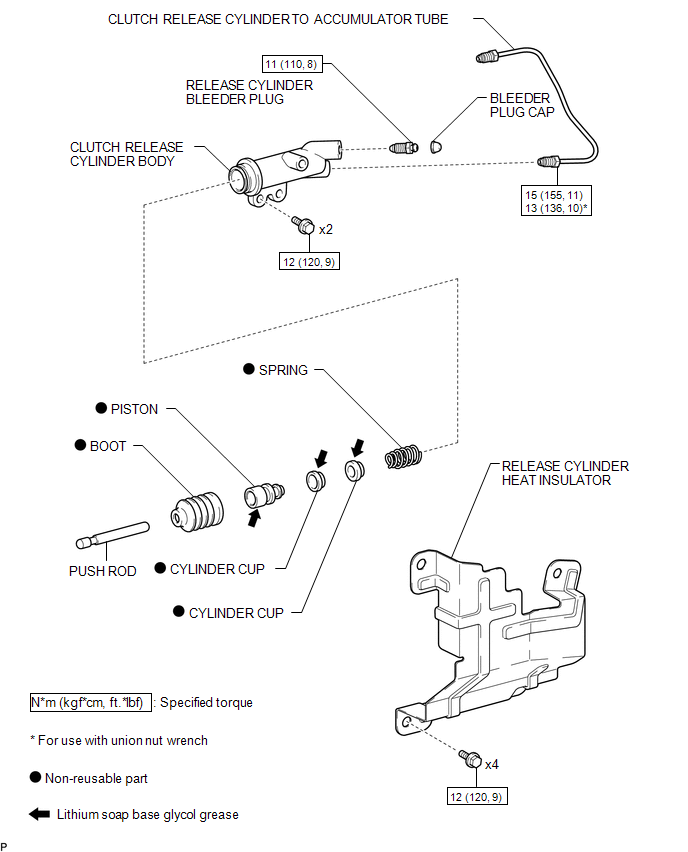
COMPONENTS
ILLUSTRATION
Disassembly
DISASSEMBLY
PROCEDURE
1. REMOVE CLUTCH RELEASE CYLINDER KIT
(a) Remove the boot from the cylinder body.
(b) Remove the push rod from the boot.
|
(c) Using compressed air, remove the piston together with the spring from the cylinder body. NOTICE: Do not damage the inside of the cylinder body. |
|
(d) Remove the 2 cylinder cups from the piston.
2. REMOVE RELEASE CYLINDER BLEEDER PLUG
(a) Remove the bleeder plug from the cylinder body.
Removal
REMOVAL
PROCEDURE
1. DRAIN CLUTCH FLUID
2. REMOVE FRONT PROPELLER SHAFT ASSEMBLY
(See page .gif) )
)
3. REMOVE RELEASE CYLINDER HEAT INSULATOR
|
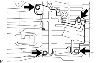
(a) Remove the 4 bolts and release cylinder heat insulator from the manual transmission assembly. |
|
4. REMOVE CLUTCH RELEASE CYLINDER TO ACCUMULATOR TUBE
|
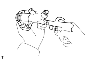
(a) Using a union nut wrench, remove the clutch release cylinder to accumulator tube from the clutch release cylinder assembly and clutch accumulator assembly. HINT: Use a container to catch the fluid. |
|
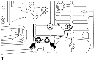
5. REMOVE CLUTCH RELEASE CYLINDER ASSEMBLY
|
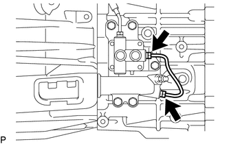
(a) Remove the 2 bolts and pull out the clutch release cylinder assembly from the manual transmission assembly. |
|
Installation
INSTALLATION
PROCEDURE
1. INSTALL CLUTCH RELEASE CYLINDER ASSEMBLY
(a) Install the clutch release cylinder assembly to the manual transmission assembly with the 2 bolts.
Torque:
12 N·m {120 kgf·cm, 9 ft·lbf}
2. INSTALL CLUTCH RELEASE CYLINDER TO ACCUMULATOR TUBE
(a) Using a union nut wrench, install the clutch release cylinder to accumulator tube to the clutch release cylinder assembly and clutch accumulator assembly.
Torque:
Specified tightening torque :
15 N·m {155 kgf·cm, 11 ft·lbf}
HINT:
- Calculate the torque wrench reading when changing the fulcrum length
of the torque wrench (See page
.gif) ).
). - When using a union nut wrench (fulcrum length of 22 mm (0.866 in.)) + torque wrench (fulcrum length of 162 mm (6.38 in.)): 13 N*m (136 kgf*cm, 10 ft.*lbf)
3. INSTALL RELEASE CYLINDER HEAT INSULATOR
(a) Install the release cylinder heat insulator to the manual transmission assembly with the 4 bolts.
Torque:
12 N·m {120 kgf·cm, 9 ft·lbf}
4. INSTALL FRONT PROPELLER SHAFT ASSEMBLY
(See page )
5. FILL RESERVOIR WITH BRAKE FLUID
6. BLEED CLUTCH LINE
7. CHECK FLUID LEVEL IN RESERVOIR
8. INSPECT FOR CLUTCH FLUID LEAK
Reassembly
REASSEMBLY
PROCEDURE
1. INSTALL RELEASE CYLINDER BLEEDER PLUG
(a) Install the bleeder plug to the cylinder body.
Torque:
11 N·m {110 kgf·cm, 8 ft·lbf}
2. INSTALL CLUTCH RELEASE CYLINDER KIT
(a) Install 2 new cylinder cups to a new piston.
(b) Install a new spring to the piston.
(c) Apply lithium soap base glycol grease to the portions indicated by the arrows in the illustration.
.png) Text in Illustration
Text in Illustration
.png) |
Lithium soap base glycol grease |
(d) Install the piston (with the spring) to the cylinder body.
NOTICE:
Do not damage the inside of the cylinder body.
(e) Install the push rod to a new boot.
(f) Install the boot (with the push rod) to the cylinder body.
 Clutch Release Cylinder(for R156f)
Components
COMPONENTS
ILLUSTRATION
Removal
REMOVAL
PROCEDURE
1. DRAIN CLUTCH FLUID
2. REMOVE FRONT PROPELLER SHAFT ASSEMBLY
(See page )
3. DISCONNECT CLUTCH RELEASE CYLINDER TO FLEXIBL ...
 Clutch Start Cancel Switch
Inspection
INSPECTION
PROCEDURE
1. INSPECT CLUTCH START CANCEL SWITCH ASSEMBLY
(a) Using an ohmmeter, check that there is resistance between terminals
2 and 4.
Standard:
10 ...
Other materials:
Engine Immobiliser System Incorrect Assembly (B279C95)
DESCRIPTION
This code is stored when an ECM that is incompatible with the engine immobiliser
system is installed to the vehicle.
DTC Code
DTC Detection Condition
Trouble Area
DTC Output Confirmation Operation
B279C95
An ECM ...
Removal
REMOVAL
PROCEDURE
1. REMOVE LOWER STEERING COLUMN COVER
2. REMOVE UPPER STEERING COLUMN COVER
3. REMOVE WINDSHIELD WIPER SWITCH ASSEMBLY
(a) Disconnect the 2 connectors.
Text in Illustration
*a
Protective Tape
...
Installation
INSTALLATION
PROCEDURE
1. INSTALL PARK/NEUTRAL POSITION SWITCH
HINT:
Make sure that the manual valve lever shaft has not been rotated prior to installing
the park/neutral position switch as the detent spring may become detached from the
manual valve lever shaft.
(a) Clean the bolt and bolt ...
