Toyota Tacoma (2005–2015) Owners Manual: Detachable pole antenna
The antenna can be removed.
■ Removing the antenna
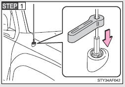
Place the included wrench around the antenna.
When not in use, the wrench is stored in glove box.
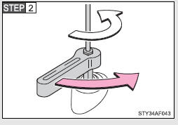
Loosen the antenna with the wrench and remove it.
■ Installing the antenna
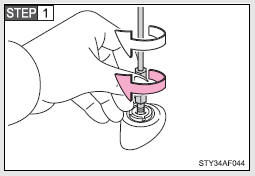
Tighten the antenna by one hand until it will not turn any more.
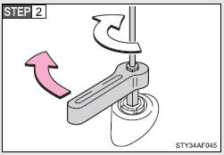
Using the wrench, tighten the antenna an additional 1/8th turn (20 to 45 degrees) to secure it in place.
After tightening the antenna, remove the wrench.
■About the wrench
●A standard 5/16 in. (8 mm) wrench can also be used to install or remove the antenna.
●After using the included wrench, store it in the glove box for safekeeping.
NOTICE
■To avoid damaging the antenna
Remove the antenna in the following situations.
●When using an automatic carwash.
●When the antenna will touch the ceiling of a garage, etc.
●When covering the vehicle with a car cover.
■Removing the antenna
●For normal driving, make sure the antenna is installed.
●When removing the antenna to use an automatic carwash, etc., be careful not to lose the antenna. Also, make sure to reinstall the antenna before driving the vehicle.
■Using the wrench
●When installing or removing the antenna, use the included wrench or a standard 5/16 in. (8 mm) wrench.
●Be careful not to scratch or damage the vehicle body with the wrench.
●Do not over-tighten the antenna.
Over-tightening may damage the antenna.
●Do not use pliers to install or remove the antenna.
Pliers may damage the antenna’s finish.
 Operating the sub woofer (on some Access Cab models)
OFF
ON
LIGHT ON
The sub woofer illumination turns on. In this position, the sub woofer operates. ...

Other materials:
Problem Symptoms Table
PROBLEM SYMPTOMS TABLE
HINT:
Use the table below to help determine the cause of problem symptoms. If multiple
suspected areas are listed, the potential causes of the symptoms are listed in order
of probability in the "Suspected Area" column of the table. Check each symptom by
check ...
What to do if...
■ Instrument cluster
■ Center panel
■Warning lights
*1: Slip indicator comes on.
*2: The indicator flashes to indicate a malfunction.
GAS STATION INFORMATION
...
Status Signal Circuit
DESCRIPTION
This circuit sends a smart key system status signal from the certification ECU
(smart key ECU assembly) to the mobile wireless charger cradle assembly. Based on
this signal, the mobile wireless charger cradle assembly suspends or resumes wireless
charging.
WIRING DIAGRAM
CAUTI ...
