Toyota Tacoma (2015-2018) Service Manual: Installation
INSTALLATION
PROCEDURE
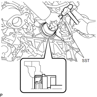
1. INSTALL REAR ENGINE OIL SEAL
(a) Apply MP grease to the lip of a new rear engine oil seal.
NOTICE:
Keep the lip free of foreign matter.
|
(b) Using SST, tap in a new rear engine oil seal until its surface is flush with the rear engine oil seal retainer edge. SST: 09223-15030 SST: 09950-70010 09951-07100 NOTICE:
|
|
2. INSTALL DRIVE PLATE AND RING GEAR SUB-ASSEMBLY (for Automatic Transmission)
.gif)
3. INSTALL FLYWHEEL SUB-ASSEMBLY (for Manual Transmission)
4. INSTALL CLUTCH DISC ASSEMBLY (for Manual Transmission)
5. INSTALL CLUTCH COVER ASSEMBLY (for Manual Transmission)
6. INSTALL AUTOMATIC TRANSMISSION ASSEMBLY (for Automatic Transmission)
|
Transmission |
See page |
|---|---|
|
AC60E |
|
|
AC60F |
|
7. INSTALL MANUAL TRANSMISSION ASSEMBLY (for Manual Transmission)
(See page )
 Removal
REMOVAL
PROCEDURE
1. REMOVE AUTOMATIC TRANSMISSION ASSEMBLY (for Automatic Transmission)
Transmission
See page
AC60E
AC60F
...
 2gr-fks Exhaust
...
Other materials:
Data List / Active Test
DATA LIST / ACTIVE TEST
1. ACTIVE TEST
HINT:
Using the Techstream to perform Active Tests allows relays, VSVs, actuators and
other items to be operated without removing any parts. This non-intrusive functional
inspection can be very useful because intermittent operation may be discovered befo ...
4WD Control ECU Communication Stop Mode
DESCRIPTION
Detection Item
Symptom
Trouble Area
4WD Control ECU Communication Stop Mode
Either condition is met:
Communication stop for "Four Wheel Drive Control" is indicated
on the "Communication Bus C ...
Freeze Frame Data
FREEZE FRAME DATA
DESCRIPTION
(a) Whenever a forward recognition camera system DTC is stored, the forward recognition
camera stores the current vehicle state (ECU and sensor information) as Freeze Frame
Data.
CHECK FREEZE FRAME DATA
(a) Connect the Techstream to the DLC3.
(b) Turn the ignit ...
