Toyota Tacoma (2015-2018) Service Manual: Replacement
REPLACEMENT
PROCEDURE
1. RECOVER REFRIGERANT FROM REFRIGERATION SYSTEM
(a) Start up the engine.
(b) Turn the A/C switch to ON.
(c) Operate the cooler compressor with an engine speed of approximately 1,000 rpm for 5 to 6 minutes to circulate the refrigerant and collect the compressor oil remaining in each component into the cooler compressor.
(d) Stop the engine.
(e) Recover the refrigerant from the A/C system using a refrigerant recovery unit.
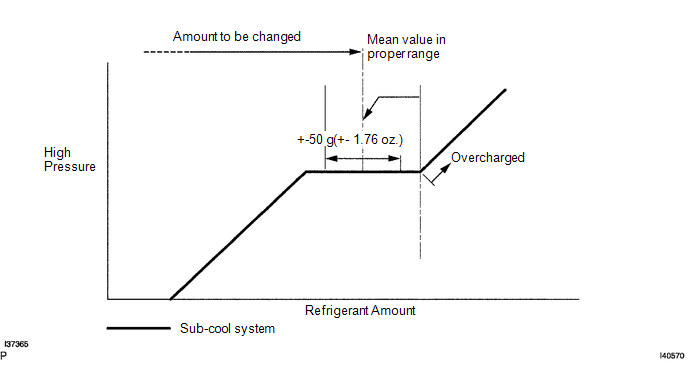
2. CHARGE AIR CONDITIONING SYSTEM WITH REFRIGERANT
(a) Perform vacuum purging using a vacuum pump.
(b) Charge refrigerant HFC-134a (R134a).
Standard:
570 to 630 g (20.10 to 22.22 oz.)
SST: 09985-20010
09985-02010
09985-02050
09985-02060
09985-02070
09985-02080
09985-02090
09985-02110
09985-02130
09985-02140
09985-02150
NOTICE:
Do not start the engine before charging it with refrigerant as the cooler compressor does not work properly without any refrigerant. This could cause the compressor to overheat.
3. WARM UP ENGINE
NOTICE:
Warm up the engine at less than 2,000 rpm for 2 minutes or more after charging it with refrigerant.
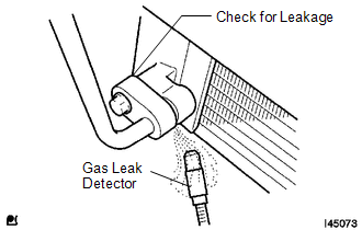
4. INSPECT FOR REFRIGERANT LEAK
(a) After recharging the refrigerant gas, check for refrigerant gas leakage using a halogen leak detector.
(b) Perform the operation under these conditions:
- Stop the engine.
- Secure good ventilation (the gas leak detector may react to volatile gases other than refrigerant, such as evaporated gasoline or exhaust gas).
- Repeat the test 2 or 3 times.
- Make sure that some refrigerant remains in the refrigeration system.
When compressor is off: approximately 392 to 588 kPa (4 to 6 kgf/cm2, 57 to 85 psi)
|
(c) Using a gas leak detector, check the refrigerant line for leakage. |
|
|
(d) Bring the gas leak detector close to the drain hose with the detector power off. HINT:
HINT: If such reaction is unavoidable, the vehicle must be lifted up. |
|
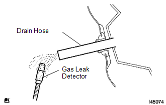
(e) If a gas leak is not detected from the drain hose, remove the blower motor control from the cooling unit. Insert the gas leak detector sensor into the unit and perform the test.
(f) Disconnect the pressure switch connector and leave it for approximately 20 minutes. Bring the gas leak detector close to the pressure switch and perform the test.
 On-vehicle Inspection
ON-VEHICLE INSPECTION
PROCEDURE
1. INSPECT REFRIGERANT PRESSURE WITH MANIFOLD GAUGE SET
(a) This is a method to specify trouble areas by using a manifold gauge set.
Read the manifold gauge pressu ...

Other materials:
Installation
INSTALLATION
PROCEDURE
1. INSTALL FORWARD RECOGNITION CAMERA
NOTICE:
When replacing the forward recognition camera, replace it with a new
one.
Do not touch the camera lens. If the camera lens has been touched, do
not use the forward recognition camera.
If the forward reco ...
Reassembly
REASSEMBLY
PROCEDURE
1. INSTALL INDICATOR LIGHT WIRE SUB-ASSEMBLY
(a) Connect the connector to install the indicator light wire sub-assembly
to the shift position indicator.
(b) Attach the clamp to install the indicator light wire sub ...
Touch Panel Switch does not Function
PROCEDURE
1.
CHECK MULTI-DISPLAY
(a) Check if there is any foreign matter caught between the display and exterior
frame of the multi-display.
OK:
No foreign matter is caught between the display and exterior frame of the multi-display.
HINT:
If there is foreig ...
