Toyota Tacoma (2015-2018) Service Manual: Data Signal Circuit between Navigation Receiver Assembly and Extension Module
DESCRIPTION
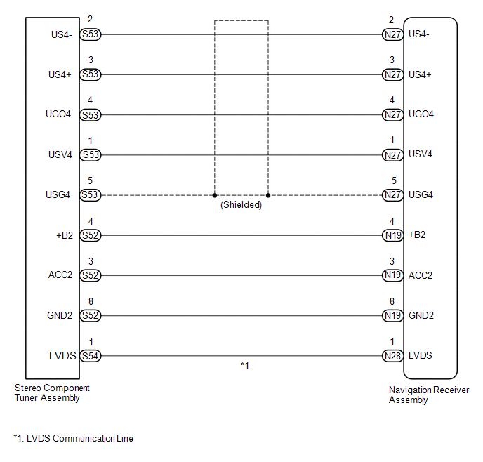
The stereo component tuner assembly sends the sound data signal or image data signal from a device to the navigation receiver assembly via this circuit.
WIRING DIAGRAM
CAUTION / NOTICE / HINT
NOTICE:
After replacing the stereo component tuner assembly of vehicles subscribed to pay-type satellite radio broadcasts, XM radio ID registration is necessary.
PROCEDURE
|
1. |
CHECK HARNESS AND CONNECTOR (NAVIGATION RECEIVER ASSEMBLY - STEREO COMPONENT TUNER ASSEMBLY) |
(a) Disconnect the N19, N27 and N28 navigation receiver assembly connectors.
(b) Disconnect the S52, S53 and S54 stereo component tuner assembly connectors.
(c) Measure the resistance according to the value(s) in the table below.
Standard Resistance:
|
Tester Connection |
Condition |
Specified Condition |
|---|---|---|
|
N27-1 (USV4) - S53-1 (USV4) |
Always |
Below 1 Ω |
|
N27-2 (US4-) - S53-2 (US4-) |
Always |
Below 1 Ω |
|
N27-3 (US4+) - S53-3 (US4+) |
Always |
Below 1 Ω |
|
N27-4 (UGO4) - S53-4 (UGO4) |
Always |
Below 1 Ω |
|
N27-5 (USG4) - S53-5 (USG4) |
Always |
Below 1 Ω |
|
N19-4 (+B2) - S52-4 (+B2) |
Always |
Below 1 Ω |
|
N19-3 (ACC2) - S52-3 (ACC2) |
Always |
Below 1 Ω |
|
N19-8 (GND2) - S52-8 (GND2) |
Always |
Below 1 Ω |
|
N28-1 (LVDS) - S54-1 (LVDS) |
Always |
Below 1 Ω |
|
N27-1 (USV4) - Body ground |
Always |
10 kΩ or higher |
|
N27-2 (US4-) - Body ground |
Always |
10 kΩ or higher |
|
N27-3 (US4+) - Body ground |
Always |
10 kΩ or higher |
|
N27-4 (UGO4) - Body ground |
Always |
10 kΩ or higher |
|
N27-5 (USG4) - Body ground |
Always |
10 kΩ or higher |
|
N19-4 (+B2) - Body ground |
Always |
10 kΩ or higher |
|
N19-3 (ACC2) - Body ground |
Always |
10 kΩ or higher |
|
N19-8 (GND2) - Body ground |
Always |
10 kΩ or higher |
|
N28-1 (LVDS) - Body ground |
Always |
10 kΩ or higher |
| NG | .gif) |
REPAIR OR REPLACE HARNESS OR CONNECTOR |
|
.gif)
|
2. |
CHECK NO. 1 NAVIGATION WIRE |
(a) Replace the No. 1 navigation wire with a known good one (See page
.gif) ).
).
(b) Check that the malfunction disappears.
OK:
Malfunction disappears.
| OK | |
END (NO. 1 NAVIGATION WIRE WAS DEFECTIVE) |
| NG | |
PROCEED TO NEXT SUSPECTED AREA SHOWN IN PROBLEM SYMPTOMS TABLE |
 Sound Signal Circuit between Radio Receiver and Stereo Jack Adapter
DESCRIPTION
The No. 1 stereo jack adapter assembly sends the sound signal from an external
device to the navigation receiver assembly via this circuit.
If there is an open or short in the circuit, ...
 Mute Signal Circuit between Radio Receiver and Stereo Component Amplifier
DESCRIPTION
This circuit sends a signal to the stereo component amplifier assembly to mute
noise. Because of that, the noise produced by changing the sound source ceases.
If there is an open in th ...
Other materials:
Transfer Case Front Oil Seal
Components
COMPONENTS
ILLUSTRATION
Replacement
REPLACEMENT
PROCEDURE
1. DRAIN TRANSFER OIL
2. SUPPORT TRANSMISSION ASSEMBLY
3. REMOVE NO. 3 FRAME CROSSMEMBER SUB-ASSEMBLY
4. REMOVE TRANSFER CASE LOWER PROTECTOR
5. REMOVE FRONT PROPELLER SHAFT ASSEMBLY
(See page )
6. ...
Four Wheel Drive (4WD) Range Signal Circuit Range / Performance (P279E)
DESCRIPTION
When the transfer position switch is switched, the 2-4 terminal and LO terminal
change to one of the following ON/OFF combinations listed in the table below.
Terminal
2WD
Between 2WD and H4
H4
Between H4 and L4
L4
...
Remote Up / Down Function does not Operate
DESCRIPTION
When the ignition switch is ON, the power window regulator master switch assembly
sends remote up/down signals to each power window regulator motor assembly via the
LIN communication line.
WIRING DIAGRAM
CAUTION / NOTICE / HINT
NOTICE:
The power window control system u ...
