Toyota Tacoma (2015-2018) Service Manual: Engine Oil Cooler
Components
COMPONENTS
ILLUSTRATION
ILLUSTRATION
ILLUSTRATION
Inspection
INSPECTION
PROCEDURE
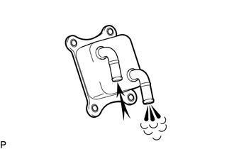
1. INSPECT OIL COOLER ASSEMBLY
|
(a) Check the oil cooler assembly for damage and clogging. If necessary, replace the oil cooler assembly. |
|
Installation
INSTALLATION
PROCEDURE
1. INSTALL OIL COOLER ASSEMBLY
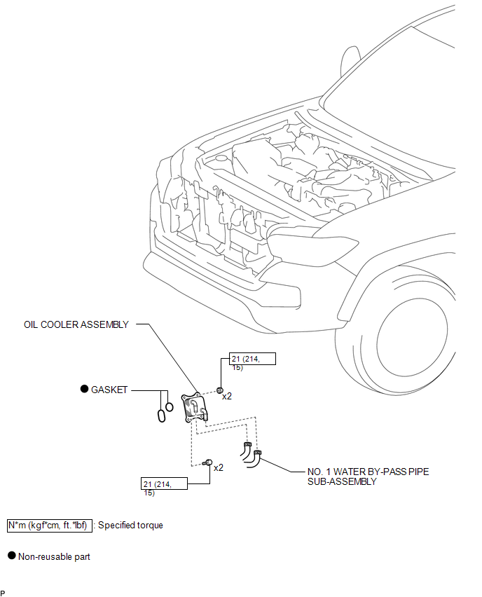
(a) Install 2 new gaskets to the oil bracket sub-assembly.
(b) Install the oil cooler assembly with the 2 bolts and 2 nuts.
Torque:
21 N·m {214 kgf·cm, 15 ft·lbf}
2. CONNECT NO. 1 WATER BY-PASS PIPE SUB-ASSEMBLY
(a) Connect the No. 1 water by-pass pipe sub-assembly.
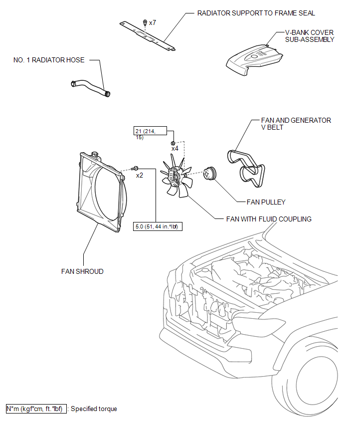
3. INSTALL FAN SHROUD
.gif)
4. INSTALL NO. 1 RADIATOR HOSE
5. INSTALL V-BANK COVER SUB-ASSEMBLY
6. ADD ENGINE OIL
7. CHECK ENGINE OIL LEVEL
8. ADD ENGINE COOLANT
9. INSPECT FOR ENGINE OIL LEAK
10. INSPECT FOR COOLANT LEAK
11. INSTALL RADIATOR SUPPORT TO FRAME SEAL
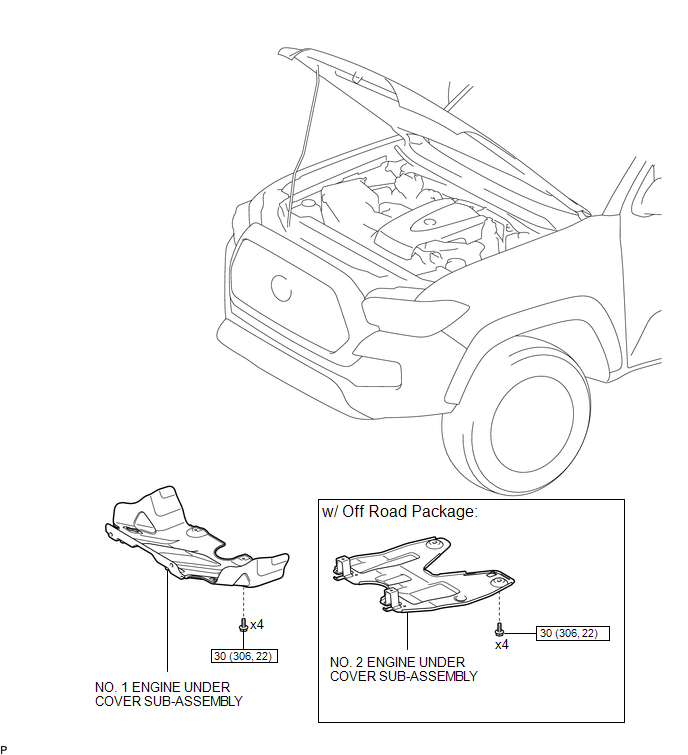
12. INSTALL NO. 1 ENGINE UNDER COVER SUB-ASSEMBLY
13. INSTALL NO. 2 ENGINE UNDER COVER SUB-ASSEMBLY (w/ Off Road Package)
Removal
REMOVAL
PROCEDURE
1. REMOVE NO. 2 ENGINE UNDER COVER SUB-ASSEMBLY (w/ Off Road Package)
2. REMOVE NO. 1 ENGINE UNDER COVER SUB-ASSEMBLY
3. REMOVE RADIATOR SUPPORT TO FRAME SEAL
.gif)
4. DRAIN ENGINE COOLANT
5. DRAIN ENGINE OIL
6. REMOVE V-BANK COVER SUB-ASSEMBLY
7. REMOVE NO. 1 RADIATOR HOSE
8. REMOVE FAN SHROUD
9. DISCONNECT NO. 1 WATER BY-PASS PIPE SUB-ASSEMBLY
(a) Disconnect the No.1 water by-pass pipe sub-assembly.
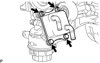
10. REMOVE OIL COOLER ASSEMBLY
|
(a) Remove the 2 bolts, 2 nuts and oil cooler assembly. |
|
(b) Remove the 2 gaskets.

 Lubrication System
On-vehicle Inspection
ON-VEHICLE INSPECTION
PROCEDURE
1. INSPECT ENGINE OIL LEVEL
(a) Warm up the engine, and then stop the engine and wait for 5 minutes.
(b) Check that the engine oil level is ...
Other materials:
Voice Guidance does not Function
PROCEDURE
1.
CHECK VOICE GUIDANCE SETTING
(a) Check that the voice guidance settings are not off.
OK:
Voice guidance settings are not off.
NG
CHANGE VOICE GUIDANCE SETTINGS TO ON
OK
...
Navigation Receiver Assembly Communication Stop Mode
DESCRIPTION
Detection Item
Symptom
Trouble Area
Navigation Receiver Assembly Communication Stop Mode
Either condition is met:
Communication stop for "Display and Navigation (AVN1)" is indicated
on the "C ...
Diagnostic Trouble Code Chart
DIAGNOSTIC TROUBLE CODE CHART
TOUCH SELECT 2-4 AND HIGH-LOW SYSTEM
DTC Code
Detection Item
See page
P163B
4WD ECU Malfunction
P17A0
Automatic Disconnecting Differential Motor Control Circuit Open
...
