Toyota Tacoma (2015-2018) Service Manual: Skid Control Buzzer Circuit (C1A4A)
DESCRIPTION
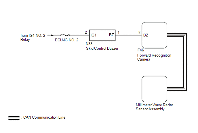
The millimeter wave radar sensor assembly is connected to the forward recognition camera via CAN communication.
The millimeter wave radar sensor assembly operates the pre-collision alarm by sending a buzzer request signal to the skid control buzzer.
If the millimeter wave radar sensor assembly detects a malfunction in the skid control buzzer circuit, it stores DTC C1A4A.
|
DTC No. |
Detection Item |
DTC Detection Condition |
Trouble Area |
|---|---|---|---|
|
C1A4A |
Skid Control Buzzer Circuit |
When the ignition switch is ON and the pre-collision alarm is operating, either of the following conditions is met:
|
|
WIRING DIAGRAM
CAUTION / NOTICE / HINT
NOTICE:
- Inspect the fuses for circuits related to this system before performing the following procedure.
- When replacing the millimeter wave radar sensor assembly, always replace it with a new one.
- When the millimeter wave radar sensor assembly is replaced with a new
one, adjustment of the radar sensor beam axis must be performed.
Click here
.gif)
- If the forward recognition camera has been replaced with a new one,
be sure to perform forward recognition axis adjustment.
Click here
- When a malfunction occurs in the communication line to the forward recognition
camera, U023A and/or U1002 is output. If a DTC related to the CAN communication
line is output, first troubleshoot the CAN communication line.
Click here
PROCEDURE
|
1. |
CHECK FOR DTCs (PRE-COLLISION SYSTEM) |
(a) Clear the DTCs.
Click here
(b) Perform the Active Test according to the display on the Techstream.
Click here
NOTICE:
Perform the Active Test for 1 second or more.
HINT:
Performing the Active Test for 1 second or more causes DTC C1A4A to be stored if the DTC detection conditions are met.
Body Electrical > Pre-Collision 2 > Data List|
Tester Display |
Measurement Item |
Range |
Normal Condition |
Diagnostic Note |
|---|---|---|---|---|
|
PCS Crash Alarm Buzzer |
Skid control buzzer status |
ON or OFF |
ON: Skid control buzzer sounding OFF: Skid control buzzer not sounding |
- |
(c) Check for DTCs.
Click here
|
Result |
Proceed to |
|---|---|
|
DTC C1A4A is not output |
A |
|
DTC C1A4A is output |
B |
| A | .gif) |
USE SIMULATION METHOD TO CHECK |
|
.gif)
|
2. |
CHECK TERMINAL VOLTAGE |
|
(a) Disconnect the skid control buzzer connector. |
|
(b) Measure the voltage according to the value(s) in the table below.
Standard Voltage:
|
Tester Connection |
Switch Condition |
Specified Condition |
|---|---|---|
|
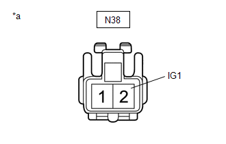
N38-2 (IG1) - Body ground |
Ignition switch ON |
11 to 14 V |
|
Ignition switch off |
Below 1 V |
(c) Connect the skid control buzzer connector.
| NG | |
REPAIR OR REPLACE HARNESS OR CONNECTOR (SKID CONTROL BUZZER - BATTERY) |
|
|
3. |
CHECK HARNESS AND CONNECTOR (SKID CONTROL BUZZER - FORWARD RECOGNITION CAMERA) |
(a) Disconnect the N38 skid control buzzer connector.
(b) Disconnect the F46 forward recognition camera connector.
(c) Measure the resistance according to the value(s) in the table below.
Standard Resistance:
|
Tester Connection |
Condition |
Specified Condition |
|---|---|---|
|
N38-1 (BZ) - F46-8 (BZ) |
Always |
Below 1 Ω |
|
N38-1 (BZ) or F46-8 (BZ) - Body ground |
Always |
10 kΩ or higher |
(d) Connect the F46 forward recognition camera connector.
(e) Connect the N38 skid control buzzer connector.
| OK | |
GO TO STEP 6 |
|
|
4. |
REPAIR OR REPLACE HARNESS OR CONNECTOR (SKID CONTROL BUZZER - FORWARD RECOGNITION CAMERA) |
(a) Repair or replace the harness or connector.
|
|
5. |
CHECK FOR DTCs (PRE-COLLISION SYSTEM) |
(a) Clear the DTCs.
Click here
(b) Perform the Active Test according to the display on the Techstream.
Click here
NOTICE:
Perform the Active Test for 1 second or more.
HINT:
Performing the Active Test for 1 second or more causes DTC C1A4A to be stored if the DTC detection conditions are met.
Body Electrical > Pre-Collision 2 > Data List|
Tester Display |
Measurement Item |
Range |
Normal Condition |
Diagnostic Note |
|---|---|---|---|---|
|
PCS Crash Alarm Buzzer |
Skid control buzzer status |
ON or OFF |
ON: Skid control buzzer sounding OFF: Skid control buzzer not sounding |
- |
(c) Check for DTCs.
Click here
|
Result |
Proceed to |
|---|---|
|
DTC C1A4A is not output |
A |
|
DTC C1A4A is output |
B |
| A | |
END |
|
|
6. |
INSPECT SKID CONTROL BUZZER (CONFIRM BUZZER OPERATION) |
(a) Turn the ignition switch to ON.
(b) Check if the skid control buzzer is sounding.
|
Result |
Proceed to |
|---|---|
|
The skid control buzzer does not sound when the ignition switch is ON |
A |
|
The skid control buzzer sounds continuously when the ignition switch is ON |
B |
| B | |
GO TO STEP 8 |
|
|
7. |
INSPECT SKID CONTROL BUZZER (UNIT INSPECTION) |
(a) Remove the skid control buzzer.
Click here
(b) Inspect the skid control buzzer.
Click here
|
Result |
Proceed to |
|---|---|
|
Skid control buzzer is abnormal |
A |
|
Skid control buzzer is normal |
B |
| B | |
GO TO STEP 9 |
|
|
8. |
REPLACE SKID CONTROL BUZZER |
(a) Replace the skid control buzzer.
Click here
|
|
9. |
CHECK FOR DTCs (PRE-COLLISION SYSTEM) |
(a) Clear the DTCs.
Click here
(b) Perform the Active Test according to the display on the Techstream.
Click here
NOTICE:
Perform the Active Test for 1 second or more.
HINT:
Performing the Active Test for 1 second or more causes DTC C1A4A to be stored if the DTC detection conditions are met.
Body Electrical > Pre-Collision 2 > Data List|
Tester Display |
Measurement Item |
Range |
Normal Condition |
Diagnostic Note |
|---|---|---|---|---|
|
PCS Crash Alarm Buzzer |
Skid control buzzer status |
ON or OFF |
ON: Skid control buzzer sounding OFF: Skid control buzzer not sounding |
- |
(c) Check for DTCs.
Click here
|
Result |
Proceed to |
|---|---|
|
DTC C1A4A is not output |
A |
|
DTC C1A4A is output |
B |
| A | |
END |
|
|
10. |
REPLACE FORWARD RECOGNITION CAMERA |
(a) Replace the forward recognition camera.
Click here
(b) Perform forward recognition axis adjustment.
Click here
|
|
11. |
CHECK FOR DTCs (PRE-COLLISION SYSTEM) |
(a) Clear the DTCs.
Click here
(b) Perform the Active Test according to the display on the Techstream.
Click here
NOTICE:
Perform the Active Test for 1 second or more.
HINT:
Performing the Active Test for 1 second or more causes DTC C1A4A to be stored if the DTC detection conditions are met.
Body Electrical > Pre-Collision 2 > Data List|
Tester Display |
Measurement Item |
Range |
Normal Condition |
Diagnostic Note |
|---|---|---|---|---|
|
PCS Crash Alarm Buzzer |
Skid control buzzer status |
ON or OFF |
ON: Skid control buzzer sounding OFF: Skid control buzzer not sounding |
- |
(c) Check for DTCs.
Click here
|
Result |
Proceed to |
|---|---|
|
DTC C1A4A is not output |
A |
|
DTC C1A4A is output |
B |
| A | |
END (FORWARD RECOGNITION CAMERA WAS DEFECTIVE) |
|
|
12. |
REPLACE MILLIMETER WAVE RADAR SENSOR ASSEMBLY |
(a) Replace the millimeter wave radar sensor assembly.
Click here
(b) Adjust the millimeter wave radar sensor assembly.
Click here
|
|
13. |
CLEAR DTC (PRE-COLLISION SYSTEM) |
(a) Clear the DTCs.
Click here
| NEXT | |
END (MILLIMETER WAVE RADAR SENSOR ASSEMBLY WAS DEFECTIVE) |
 Brake Control Signal Mismatch (C1A69)
DESCRIPTION
The skid control ECU (master cylinder solenoid)*1 or skid control ECU (brake
actuator assembly)*2 sends signals to the millimeter wave radar sensor assembly
according to the brake con ...
 Stop Light Relay Circuit (C1A4B)
DESCRIPTION
The skid control ECU (master cylinder solenoid)*1 or skid control ECU (brake
actuator assembly)*2 sends a stop light operation request signal to the stop light
relay (stop light switc ...
Other materials:
Traffic Information is not Displayed
CAUTION / NOTICE / HINT
NOTICE:
Traffic information requires payment. An "XM Nav Traffic" contract must
be made between the satellite radio company and the user. If the contract
expires, traffic information will not be available.
Traffic information does not apply to ...
Diagnostic Trouble Code Chart
DIAGNOSTIC TROUBLE CODE CHART
If a DTC is displayed during the DTC check, check the circuit listed for the
DTC in the table below (refer to the appropriate page).
HINT:
When the SRS warning light remains on and the normal system code is
output, a decrease in the source voltage is li ...
Perchlorate Material
Special handling may apply, See www.dtsc.ca.gov/hazardouswaste/perchlorate.
Your vehicle has components that may contain perchlorate. These components may
include airbag, seat belt pretensioners, and wireless remote control batteries.
CAUTION
■General precautions while driving
Driving un ...
