Toyota Tacoma (2015-2018) Service Manual: Multi-terrain Select Indicator Light Remains ON
DESCRIPTION
Refer to Multi-terrain Select Indicator Light does not Come ON (See page
.gif) ).
).
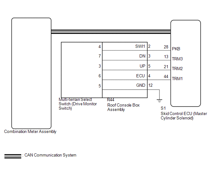
WIRING DIAGRAM
CAUTION / NOTICE / HINT
NOTICE:
- When replacing the skid control ECU (master cylinder solenoid), perform
calibration (See page
).
- Inspect the fuses for circuits related to this system before performing the following inspection procedure.
PROCEDURE
|
1. |
CHECK CAN COMMUNICATION SYSTEM |
| NG | .gif) |
GO TO CAN COMMUNICATION SYSTEM (HOW TO PROCEED WITH TROUBLESHOOTING) |
|
.gif)
|
2. |
CHECK DTC |
(a) Check for DTCs (See page
).
|
Result |
Proceed to |
|---|---|
|
DTC is not output |
A |
|
DTC is output |
B |
| B | |
REPAIR CIRCUITS INDICATED BY OUTPUT DTCS |
|
|
3. |
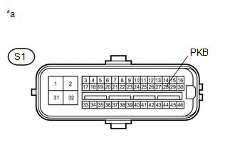
INSPECT SKID CONTROL ECU (PKB TERMINAL) |
(a) Disconnect the S1 skid control ECU (master cylinder solenoid) connector.
|
(b) Measure the resistance according to the value(s) in the table below. Standard Resistance:
|
|
(c) Reconnect the S1 skid control ECU (master cylinder solenoid) connector.
| NG | |
GO TO STEP 5 |
|
|
4. |
REPLACE COMBINATION METER ASSEMBLY |
(a) Replace the combination meter assembly a new one.
OK:
The multi-terrain select indicator light turns on or off in accordance with the switch operation.
| OK | |
REPLACE MASTER CYLINDER SOLENOID |
| NG | |
END |
|
5. |
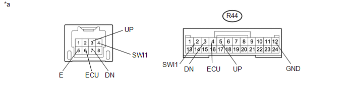
INSPECT DRIVE MONITOR SWITCH |
(a) Remove the multi-terrain select switch (drive monitor switch) (See page
).
(b) Inspect the multi-terrain select (drive monitor switch) (See page
).
| NG | |
REPLACE DRIVE MONITOR SWITCH |
|
|
6. |
INSPECT ROOF CONSOLE BOX ASSEMBLY |
(a) Remove the roof console box assembly.
- for Double Cab: (See page
)
- for Access Cab: (See page
)
 Text in Illustration
|
*a |
Component without harness connected (Roof Console Box Assembly) |
- |
- |
(b) Measure the resistance according the value(s) in the table below.
Standard Resistance:
|
Tester Connection |
Condition |
Specified Condition |
|---|---|---|
|
R44-2 (SWI1) - 4 |
Always |
Below 1 Ω |
|
R44-3 (DN) - 7 |
Always |
Below 1 Ω |
|
R44-4 (ECU) - 6 |
Always |
Below 1 Ω |
|
R44-5 (UP) - 3 |
Always |
Below 1 Ω |
|
R44-12 (GND) - 5 |
Always |
Below 1 Ω |
|
Result |
Proceed to |
|---|---|
|
OK |
A |
|
NG (for Double Cab) |
B |
|
NG (for Access Cab) |
C |
| A | |
REPAIR OR REPLACE HARNESS OR CONNECTOR (MASTER CYLINDER SOLENOID - ROOF CONSOLE BOX ASSEMBLY) |
| B | |
REPLACE ROOF CONSOLE BOX ASSEMBLY |
| C | |
REPLACE ROOF CONSOLE BOX ASSEMBLY |
 Multi-terrain Select Indicator Light does not Come ON
DESCRIPTION
When the transfer gear position is L4, the multi-terrain select indicator light
illuminates and control begins.
Under any of the following conditions, the multi-terrain select system d ...
 Brake Warning Light does not Come ON
DESCRIPTION
Refer to Brake Warning Light Remains ON (See page
).
WIRING DIAGRAM
Refer to Brake Warning Light Remains ON (See page
).
CAUTION / NOTICE / HINT
NOTICE:
When replacing th ...
Other materials:
Vehicle Information Not Obtained (C1A02)
DESCRIPTION
When a new millimeter wave radar sensor assembly is installed, it receives vehicle
specification information (destination, steering wheel position, 2WD or 4WD, etc.)
from the main body ECU (multiplex network body ECU) and stores the information.
DTC C1A02 is stored when the millime ...
Clutch start cancel switch
The switch allows the vehicle to be driven out of difficult situations by cranking
the engine with the clutch engaged.
Never use the switch for normal engine starting. Be sure to follow the starting
procedure.
Press the CLUTCH START CANCEL switch to cancel the clutch start system when the
...
Electrical Key Oscillator(for Rear Floor)
Components
COMPONENTS
ILLUSTRATION
Installation
INSTALLATION
PROCEDURE
1. INSTALL NO. 2 INDOOR ELECTRICAL KEY ANTENNA ASSEMBLY
(a) Engage the clamp to install the No. 2 indoor electrical key antenna assembly.
(b) Connect the connector.
2. INSTALL REAR CONSOLE BOX ASSEMBLY
(See page ...
