Toyota Tacoma (2015-2018) Service Manual: Transponder Key Ecu
Components
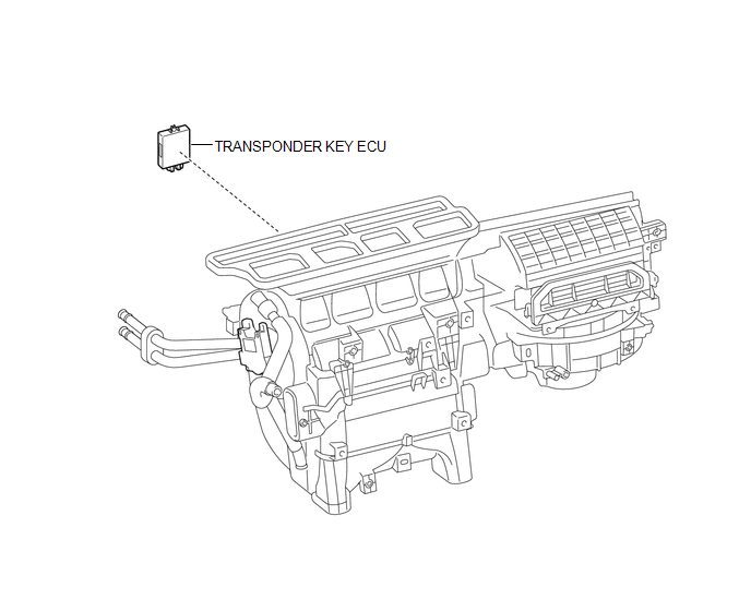
COMPONENTS
ILLUSTRATION
Installation
INSTALLATION
PROCEDURE
1. INSTALL TRANSPONDER KEY ECU
|
(a) Engage the 2 guides to move the transponder key ECU in the direction of the arrow to install the transponder key ECU. |
|
2. INSTALL AIR CONDITIONING UNIT ASSEMBLY
(See page .gif) )
)
Removal
REMOVAL
PROCEDURE
1. REMOVE AIR CONDITIONING UNIT ASSEMBLY
(See page .gif) )
)
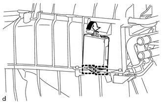
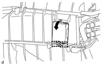
2. REMOVE TRANSPONDER KEY ECU
|
(a) Move the transponder key ECU in the direction of the arrow to disengage the 2 guides to remove the transponder key ECU. |
|
 Transponder Key Amplifier
Components
COMPONENTS
ILLUSTRATION
Installation
INSTALLATION
PROCEDURE
1. INSTALL TRANSPONDER KEY COIL
(a) Engage the 2 claws to install the transponder key coil.
...
 Exterior
...
Other materials:
Cruise Control Input Processor (P160700)
DESCRIPTION
The ECM continuously monitors its main and sub CPUs. This self-check ensures
that the ECM is functioning properly. If outputs from the CPUs are different and
deviate from the standard, the ECM will illuminate the MIL and store the DTC.
DTC No.
Detection Item
...
Brake Switch "A" Circuit Open (P057113)
DESCRIPTION
DTC No.
DTC Detection Condition
Trouble Area
MIL
Note
P057113
Vehicle Condition:
Cruise control operating
Malfunction Status:
Stop light switch assembly circuit malfunction ...
System Description
SYSTEM DESCRIPTION
1. WIRELESS CHARGER FUNCTION OUTLINE
(a) The wireless charging system enables Qi-compliant* rechargeable devices,
such as a cellular phone, to be recharged by merely placing it on the charging area
of the mobile wireless charger cradle assembly on the console panel.
HINT:
...
