Toyota Tacoma (2015-2018) Service Manual: Security Horn Assembly
Components
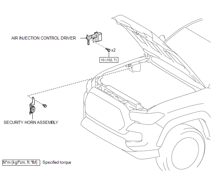
COMPONENTS
ILLUSTRATION
Inspection
INSPECTION
PROCEDURE
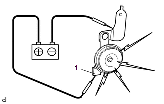
1. INSPECT SECURITY HORN ASSEMBLY
|
(a) Check the operation. (1) Apply battery voltage and check operation of the security horn assembly. OK:
If the result is not as specified, replace the security horn assembly. |
|
Removal
REMOVAL
PROCEDURE
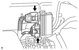
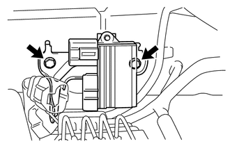
1. REMOVE AIR INJECTION CONTROL DRIVER (for 2TR-FE)
|
(a) Disconnect the 2 connectors. |
|
|
(b) Remove the 2 bolts and air injection control driver. |
|
2. REMOVE SECURITY HORN ASSEMBLY
|
(a) Disconnect the connector. |
|
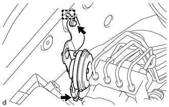
(b) Remove the bolt.
(c) Disengage the guide to remove the security horn assembly.
Installation
INSTALLATION
PROCEDURE
1. INSTALL SECURITY HORN ASSEMBLY
(a) Engage the guide to install the security horn assembly.
(b) Install the bolt.
(c) Connect the connector.
2. INSTALL AIR INJECTION CONTROL DRIVER (for 2TR-FE)
(a) Install the air injection control driver with the 2 bolts.
Torque:
10 N·m {102 kgf·cm, 7 ft·lbf}
(b) Connect the 2 connectors.
 Engine Hood Courtesy Switch
Components
COMPONENTS
ILLUSTRATION
Inspection
INSPECTION
PROCEDURE
1. INSPECT HOOD COURTESY SWITCH (HOOD LOCK ASSEMBLY)
(a) Check the resistance.
(1) Measure the resistance ac ...

Other materials:
Voice Guidance does not Function
PROCEDURE
1.
CHECK VOICE GUIDANCE SETTING
(a) Check that the voice guidance settings are not off.
OK:
Voice guidance settings are not off.
NG
CHANGE VOICE GUIDANCE SETTINGS TO ON
OK
...
On-vehicle Inspection
ON-VEHICLE INSPECTION
PROCEDURE
1. INSPECT FUEL CUT OPERATION
(a) Start the engine and warm it up.
(b) Increase the engine speed to at least 3500 rpm.
(c) Use a sound scope to check for fuel injector assembly operation noise.
(d) Check that when the accelerator pedal is released, fuel injector ...
TC and CG Terminal Circuit
DESCRIPTION
Connecting terminals TC and CG of the DLC3 causes the ECU to display the DTC
by blinking the ABS warning light and slip indicator light.
WIRING DIAGRAM
CAUTION / NOTICE / HINT
NOTICE:
When replacing the skid control ECU (brake actuator assembly), perform zero point
calibration ...
