Toyota Tacoma (2015-2018) Service Manual: Engine Hood Courtesy Switch
Components
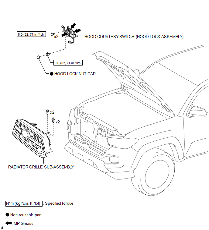
COMPONENTS
ILLUSTRATION
Inspection
INSPECTION
PROCEDURE
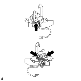
1. INSPECT HOOD COURTESY SWITCH (HOOD LOCK ASSEMBLY)
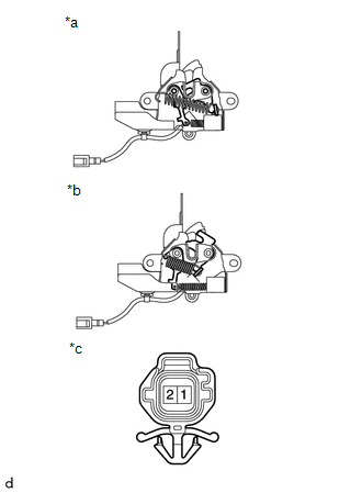
(a) Check the resistance.
|
(1) Measure the resistance according to the value(s) in the table below. Text in Illustration
Standard Resistance:
If the results are not as specified, replace the hood courtesy switch (hood lock assembly). |
|
Removal
REMOVAL
PROCEDURE
1. REMOVE RADIATOR GRILLE SUB-ASSEMBLY
(See page .gif) )
)
2. REMOVE HOOD COURTESY SWITCH (HOOD LOCK ASSEMBLY)
|
(a) Disconnect the connector. |
|
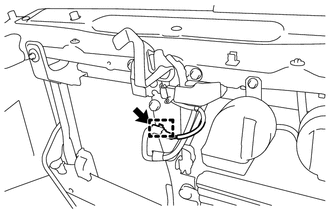
(b) Disengage the clamp to separate the wire harness.
|
(c) Using a screwdriver with its tip wrapped in protective tape, remove the hood lock nut cap. Text in Illustration
|
|

|
(d) Remove the 3 bolts to separate the hood courtesy switch (hood lock assembly). |
|
.png)
|
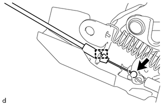
(e) Disengage the guide to disconnect the hood lock control cable assembly and remove the hood courtesy switch (hood lock assembly). |
|
Installation
INSTALLATION
PROCEDURE
1. INSTALL HOOD COURTESY SWITCH (HOOD LOCK ASSEMBLY)
|
(a) Apply MP grease to the sliding areas of the hood courtesy switch (hood lock assembly). |
|
(b) Engage the guide to connect the hood lock control cable assembly.
(c) Install the hood courtesy switch (hood lock assembly) with the 3 bolts.
Torque:
8.0 N·m {82 kgf·cm, 71 in·lbf}
(d) Install a new hood lock nut cap.
(e) Connect the connector.
(f) Engage the clamp to install the wire harness.
2. ADJUST HOOD SUB-ASSEMBLY
(See page .gif) )
)
3. INSTALL RADIATOR GRILLE SUB-ASSEMBLY
(See page
)
 Theft Deterrent
...
 Security Horn Assembly
Components
COMPONENTS
ILLUSTRATION
Inspection
INSPECTION
PROCEDURE
1. INSPECT SECURITY HORN ASSEMBLY
(a) Check the operation.
(1) Apply battery voltage and check operation o ...
Other materials:
Front Speed Sensor
Removal
REMOVAL
PROCEDURE
1. PRECAUTION
NOTICE:
After turning the ignition switch off, waiting time may be required before disconnecting
the cable from the negative (-) battery terminal.
Therefore, make sure to read the disconnecting the cable from the negative (-)
battery terminal notic ...
Diagnostic Trouble Code Chart
DIAGNOSTIC TROUBLE CODE CHART
Intuitive Parking Assist System
DTC Code
Detection Item
See page
C1AE6
Rear Left Sensor Malfunction
C1AE7
Rear Left Center Sensor Malfunction
...
Luggage compartment features
Behind the rear seat (Double
Cab models only)
1.Cargo net hooks (vehicles with sub woofer)
2.Grocery bag hooks
3.Flashlight holder
4.Storage boxes
Deck
1. Auxiliary boxes
2. Tie-down cleats
3. Deck hooks
Auxiliary boxes
Left side
1. Turn the knob counterclockwise.
2. Open the ...
