Toyota Tacoma (2015-2018) Service Manual: Installation
INSTALLATION
PROCEDURE
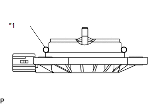
1. INSTALL CAMSHAFT TIMING OIL CONTROL SOLENOID ASSEMBLY (for Intake Side of Bank 1)
|
(a) Apply engine oil to a new O-ring and install it to the camshaft timing oil control solenoid assembly in the locations shown in the illustration. Text in Illustration
|
|
(b) Install the camshaft timing oil control solenoid assembly to the timing chain cover assembly with 2 new bolts.
Torque:
10 N·m {102 kgf·cm, 7 ft·lbf}
NOTICE:
Be careful that the O-ring is not jammed.
(c) Connect the connector to the camshaft timing oil control solenoid assembly.
2. INSTALL CAMSHAFT TIMING OIL CONTROL SOLENOID ASSEMBLY (for Exhaust Side of Bank 1)
|
(a) Apply engine oil to a new O-ring and install it to the camshaft timing oil control solenoid assembly in the locations shown in the illustration. Text in Illustration
|
|
(b) Install the camshaft timing oil control solenoid assembly to the timing chain cover assembly with 2 new bolts.
Torque:
10 N·m {102 kgf·cm, 7 ft·lbf}
NOTICE:
Be careful that the O-ring is not jammed.
(c) Connect the connector to the camshaft timing oil control solenoid assembly.
3. INSTALL CAMSHAFT TIMING OIL CONTROL SOLENOID ASSEMBLY (for Intake Side of Bank 2)
|
(a) Apply engine oil to a new O-ring and install it to the camshaft timing oil control solenoid assembly in the locations shown in the illustration. Text in Illustration
|
|
(b) Install the camshaft timing oil control solenoid assembly to the timing chain cover assembly with 2 new bolts.
Torque:
10 N·m {102 kgf·cm, 7 ft·lbf}
NOTICE:
Be careful that the O-ring is not jammed.
(c) Connect the connector to the camshaft timing oil control solenoid assembly.
4. INSTALL CAMSHAFT TIMING OIL CONTROL SOLENOID ASSEMBLY (for Exhaust Side of Bank 2)
|
(a) Apply engine oil to a new O-ring and install it to the camshaft timing oil control solenoid assembly in the locations shown in the illustration. Text in Illustration
|
|
(b) Install the camshaft timing oil control solenoid assembly to the timing chain cover assembly with 2 new bolts.
Torque:
10 N·m {102 kgf·cm, 7 ft·lbf}
NOTICE:
Be careful that the O-ring is not jammed.
(c) Connect the connector to the camshaft timing oil control solenoid assembly.
5. INSTALL THROTTLE BODY BRACKET
(a) Install the throttle body bracket to the intake air surge tank assembly and timing chain cover assembly with the 2 bolts.
Torque:
21 N·m {214 kgf·cm, 15 ft·lbf}
6. INSTALL ENGINE OIL LEVEL DIPSTICK GUIDE
(a) Apply engine oil to a new O-ring and install it to the engine oil level dipstick guide.
(b) Install the engine oil level dipstick guide to the timing chain cover assembly and oil pan sub-assembly with the bolt.
Torque:
10 N·m {102 kgf·cm, 7 ft·lbf}
(c) Engage the clamp to install the wire harness.
(d) Install the engine oil level dipstick.
7. INSTALL AIR CLEANER CAP AND HOSE
.gif)
8. INSTALL V-BANK COVER SUB-ASSEMBLY
9. INSTALL FRONT FENDER SEAL RH
HINT:
Use the same procedure as for the LH side (See page
).
 Removal
REMOVAL
PROCEDURE
1. REMOVE FRONT FENDER SEAL RH
HINT:
Use the same procedure as for the LH side (See page
).
2. REMOVE V-BANK COVER SUB-ASSEMBLY
3. REMOVE AIR CLEANER CAP AND HOSE
4. ...

Other materials:
ECU Power Source Circuit
DESCRIPTION
This circuit supplies power to the millimeter wave radar sensor assembly when
the ignition switch is ON.
WIRING DIAGRAM
CAUTION / NOTICE / HINT
NOTICE:
Inspect the fuses for circuits related to this system before performing the following
inspection procedure.
PROCEDURE
...
Reassembly
REASSEMBLY
PROCEDURE
1. INSTALL NO. 3 REAR BODY NAME PLATE (for 2GR-FKS)
2. INSTALL NO. 2 REAR BODY NAME PLATE (for 4WD)
3. INSTALL SIDE GATE SUPPORT FEMALE HINGE RH
(a) Engage the claw to install the side gate support female hinge RH.
...
Check Mode Procedure
CHECK MODE PROCEDURE
1. DESCRIPTION
(a) Check mode has a higher sensitivity to malfunctions and can detect malfunctions
that normal mode cannot detect. Check mode can also detect all the malfunctions
that normal mode can detect. In check mode, DTCs are detected with 1 trip detection
logic.
...
