Toyota Tacoma (2015-2018) Service Manual: Runnable Signal Malfunction (B2286,P0335)
DESCRIPTION
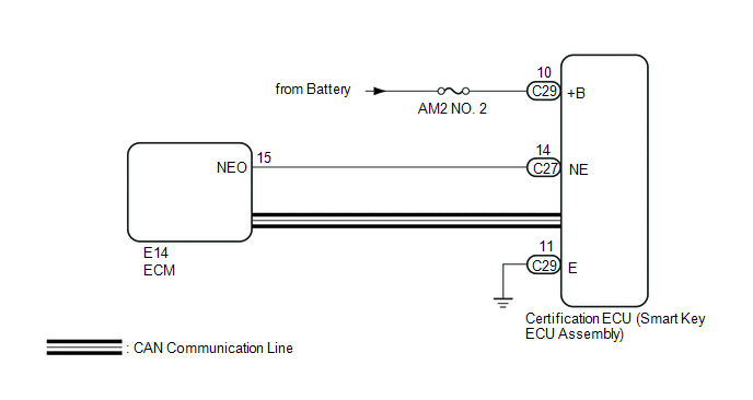
These DTCs are stored when the engine speed signal sent by the ECM via direct line and the engine speed signal sent via CAN communication do not match.
HINT:
When the cable is disconnected and reconnected to the negative (-) battery terminal, the power source mode returns to the state it was in before the cable was disconnected.
|
DTC Code |
DTC Detection Condition |
Trouble Area |
DTC Output Confirmation Operation |
|---|---|---|---|
|
B2286 |
The engine speed signal sent by the ECM via direct line and the engine speed signal sent via CAN communication (1- trip detection logic*) do not match. |
|
Disconnect the cable from the negative (-) battery terminal, wait 30 seconds and reconnect the cable to the negative (-) battery terminal. Wait 20 seconds or more with the engine switch off, then start the engine and maintain an engine speed of 1000 rpm or more for 20 seconds or more. |
|
P0335 |
The engine speed signal sent by the ECM via direct line and the engine speed signal sent via CAN communication (1- trip detection logic*) do not match. |
|
Allow the engine to idle for 10 seconds or more. |
- *: Only detected while a malfunction is present and the engine switch is on (IG)
|
Vehicle Condition when Malfunction Detected |
Fail-safe Function when Malfunction Detected |
|---|---|
|
|
WIRING DIAGRAM
CAUTION / NOTICE / HINT
NOTICE:
- When using the Techstream with the engine switch off, connect the Techstream to the DLC3 and turn a courtesy light switch on and off at intervals of 1.5 seconds or less until communication between the Techstream and the vehicle begins. Then select the vehicle type under manual mode and enter the following menus: Body Electrical / Smart Key. While using the Techstream, periodically turn a courtesy light switch on and off at intervals of 1.5 seconds or less to maintain communication between the Techstream and the vehicle.
- The smart key system (for Start Function) uses a multiplex communication
system (LIN communication system) and the CAN communication system. Inspect
the communication function by following How to Proceed with Troubleshooting.
Click here
.gif)
Troubleshoot the smart key system (for Start Function) after confirming that the communication systems are functioning properly.
- Before replacing the certification ECU (smart key ECU assembly), refer
to the smart key system (for Start Function) precaution (See page
).
- Inspect the fuses of circuits related to this system before performing the following inspection procedure.
- After performing repairs, perform the operation that fulfills the DTC output confirmation operation, and then confirm that no DTCs are output again.
|
DTC |
Data List Item |
Active Test Item |
|---|---|---|
|
B2286 P0335 |
Power Source Control
Starting Control
|
- |
PROCEDURE
|
1. |
READ VALUE USING TECHSTREAM |
(a) Connect the Techstream to the DLC3.
(b) Turn the engine switch on (IG).
(c) Turn the Techstream on.
(d) Enter the following menus: Body Electrical / Power Source Control or Starting Control / Data List.
(e) According to the display on the Techstream, read the Data List.
Power Source Control|
Tester Display |
Measurement Item/Range |
Normal Condition |
Diagnostic Note |
|---|---|---|---|
|
Engine Condition |
Engine state/Stop or Run |
Stop: Engine stopped Run: Engine running |
- |
|
Tester Display |
Measurement Item/Range |
Normal Condition |
Diagnostic Note |
|---|---|---|---|
|
Engine Speed |
Engine speed/0 to 16383 r/min |
Fluctuates in accordance with engine speed |
- |
OK:
The Data List item changes in accordance with the engine condition.
| NG | .gif) |
GO TO SFI SYSTEM (HOW TO PROCEED WITH TROUBLESHOOTING) |
|
.gif)
|
2. |
CHECK HARNESS AND CONNECTOR (POWER SOURCE) |
| NG | |
REPAIR OR REPLACE HARNESS OR CONNECTOR IN CIRCUIT CONNECTED TO POWER SOURCE |
|
|
3. |
CHECK HARNESS AND CONNECTOR (GROUND) |
| NG | |
REPAIR OR REPLACE HARNESS OR CONNECTOR |
|
|
4. |
CHECK HARNESS AND CONNECTOR (CERTIFICATION ECU (SMART KEY ECUASSEMBLY) - ECM) |
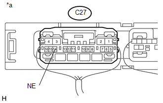
(a) Disconnect the C27 certification ECU (smart key ECU assembly) connector.
(b) Disconnect the E14 ECM connector.
(c) Measure the resistance according to the value(s) in the table below.
Standard Resistance:
|
Tester Connection |
Condition |
Specified Condition |
|---|---|---|
|
C27-14 (NE) - E14-15 (NEO) |
Always |
Below 1 Ω |
|
C27-14 (NE) - E14-15 (NEO) - Body ground |
Always |
10 kΩ or higher |
| NG | |
REPAIR OR REPLACE HARNESS OR CONNECTOR |
|
|
5. |
CHECK CERTIFICATION ECU (SMART KEY ECU ASSEMBLY) |
(a) Reconnect the C27 certification ECU (smart key ECU assembly) connector.
(b) Reconnect the E14 ECM connector.
|
(c) Using an oscilloscope, check the engine speed input signal waveform at the terminal of the certification ECU (smart key ECU assembly). Standard Frequency:
|
|
| OK | |
REPLACE CERTIFICATION ECU (SMART KEY ECU ASSEMBLY) |
| NG | |
GO TO SFI SYSTEM (HOW TO PROCEED WITH TROUBLESHOOTING) |
 Diagnostic Trouble Code Chart
DIAGNOSTIC TROUBLE CODE CHART
Smart Key System (for Start Function)
DTC Code
Detection Item
See page
B2271
Ignition Hold Monitor Malfunct ...
 Lost Communication with ECM / PCM (U0100,U0140,U0142,U0155,U1117)
DESCRIPTION
These DTCs are stored when there is a CAN communication malfunction between the
certification ECU (smart key ECU assembly), ECM, main body ECU (multiplex network
body ECU) or combinat ...
Other materials:
Vanity Light
Components
COMPONENTS
ILLUSTRATION
Removal
REMOVAL
CAUTION / NOTICE / HINT
HINT:
Use the same procedures for the LH and RH side.
The procedures listed below are for the LH side.
PROCEDURE
1. REMOVE VISOR ASSEMBLY
(a) Disengage the guide to separate the vi ...
Removal
REMOVAL
PROCEDURE
1. REMOVE FRONT DOOR SCUFF PLATE LH (for Double Cab)
Click here
2. REMOVE FRONT DOOR SCUFF PLATE LH (for Access Cab)
Click here
3. REMOVE COWL SIDE TRIM BOARD LH
Click here
4. REMOVE INSTRUMENT CLUSTER CENTER FINISH PANEL SUB-ASSEMBLY
Click here
5. REMOVE INSTRUME ...
Cargo Light Circuit
DESCRIPTION
The main body ECU (multiplex network body ECU) receives a cargo light information
signal from the deck light switch assembly and door courtesy light switch, and illuminates
the cargo light.
WIRING DIAGRAM
CAUTION / NOTICE / HINT
NOTICE:
Inspect the fuses for circuits r ...
