Toyota Tacoma (2015-2018) Service Manual: Installation
INSTALLATION
PROCEDURE
1. INSTALL REAR SEATBACK HINGE SUB-ASSEMBLY
(a) Install the rear seatback hinge sub-assembly with the 2 bolts.
Torque:
30 N·m {306 kgf·cm, 22 ft·lbf}
2. INSTALL REAR SEATBACK ASSEMBLY
(a) Install the rear seatback assembly with the 2 bolts.
Torque:
37 N·m {377 kgf·cm, 27 ft·lbf}
|
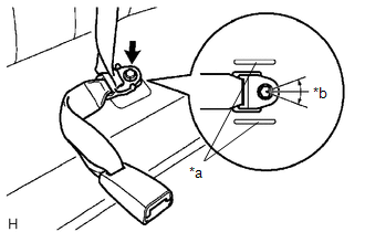
(b) Connect the rear seat inner belt assembly and rear center seat outer belt assembly by installing the floor anchor with the bolt. Text in Illustration
Torque: 42 N·m {428 kgf·cm, 31 ft·lbf} NOTICE:
|
|
3. INSTALL REAR SEATBACK HINGE COVER
(a) Engage the 6 claws to install the 2 rear seatback hinge covers.
4. INSTALL REAR SEAT CUSHION ASSEMBLY
(a) Install the rear seat cushion with the 2 bolts.
Torque:
37 N·m {377 kgf·cm, 27 ft·lbf}
 Removal
REMOVAL
PROCEDURE
1. REMOVE REAR SEAT CUSHION ASSEMBLY
(a) Remove the 2 bolts and rear seat cushion assembly.
2. REMOVE REAR SEATBACK HINGE COV ...
 Reassembly
REASSEMBLY
CAUTION / NOTICE / HINT
CAUTION:
Wear protective gloves. Sharp areas on the parts may injure your hands.
PROCEDURE
1. INSTALL SEPARATE TYPE REAR SEATBACK COVER
(a) Using ho ...
Other materials:
Windshield wipers and washer
■ Without intermittent type
Type A
Low speed windshield wiper
operation
High speed windshield wiper operation
Temporary operation
Washer operation
Type B
Low speed windshield wiper operation
High speed windshield wiper operation
Temporary operation
Washer op ...
Four Wheel Drive (4WD) Low Switch Circuit Range / Performance (P2772)
DESCRIPTION
This DTC is output when a malfunction in the L4 detection switch is detected.
DTC No.
Detection Item
DTC Detection Condition
Trouble Area
P2772
Four Wheel Drive (4WD) Low Switch Circuit Range / Performance
...
Power Outlet Socket(for Front Side)
Components
COMPONENTS
ILLUSTRATION
Removal
REMOVAL
PROCEDURE
1. REMOVE INSTRUMENT PANEL LOWER CENTER FINISH PANEL
(See page )
2. REMOVE NO. 1 POWER OUTLET SOCKET ASSEMBLY
(a) Using a screwdriver with its tip wrapped in protective tape, disengage
the 2 claws to remove t ...
