Toyota Tacoma (2015-2018) Service Manual: Removal
REMOVAL
PROCEDURE
1. REMOVE ENGINE ASSEMBLY
(See page .gif) )
)
2. REMOVE IGNITION COIL ASSEMBLY
3. REMOVE ENGINE OIL LEVEL DIPSTICK GUIDE
4. REMOVE CAMSHAFT TIMING OIL CONTROL SOLENOID ASSEMBLY (for Intake Side of Bank 1)
5. REMOVE CAMSHAFT TIMING OIL CONTROL SOLENOID ASSEMBLY (for Exhaust Side of Bank 1)
6. REMOVE CAMSHAFT TIMING OIL CONTROL SOLENOID ASSEMBLY (for Intake Side of Bank 2)
7. REMOVE CAMSHAFT TIMING OIL CONTROL SOLENOID ASSEMBLY (for Exhaust Side of Bank 2)
8. REMOVE NO. 1 WATER BY-PASS PIPE SUB-ASSEMBLY (w/ Oil Cooler)
9. REMOVE NO. 5 WATER BY-PASS HOSE
10. REMOVE NO. 1 WATER BY-PASS HOSE
11. REMOVE NO. 2 WATER BY-PASS HOSE
12. REMOVE NO. 3 WATER BY-PASS HOSE
13. REMOVE WATER OUTLET
14. REMOVE NO. 1 IDLER PULLEY SUB-ASSEMBLY
15. REMOVE NO. 2 IDLER PULLEY SUB-ASSEMBLY
16. REMOVE V-RIBBED BELT TENSIONER ASSEMBLY
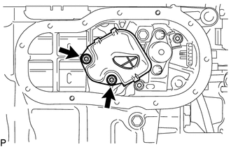
17. DISCONNECT ENGINE OIL PRESSURE SWITCH ASSEMBLY CONNECTOR
|
(a) Disengage the clamp and disconnect the connector from the engine oil pressure switch assembly. |
|
.png)
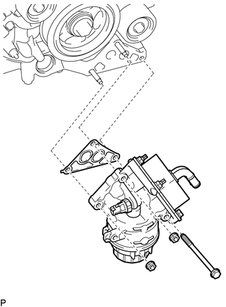
18. REMOVE OIL FILTER BRACKET SUB-ASSEMBLY (w/ Oil Cooler)
|
(a) Remove the 2 nuts, bolt, oil filter bracket sub-assembly and gasket. |
|
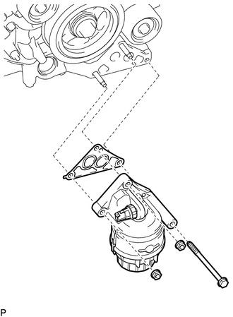
19. REMOVE OIL FILTER BRACKET SUB-ASSEMBLY (w/o Oil Cooler)
|
(a) Remove the 2 nuts, bolt, oil filter bracket sub-assembly and gasket. |
|
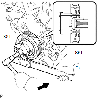
20. REMOVE CRANKSHAFT PULLEY
(a) Using SST, hold the crankshaft pulley and loosen the pulley set bolt. Continue to loosen the bolt until only 2 or 3 threads are screwed into the crankshaft.
 Text in Illustration
|
*a |
Hold |
.png) |
Turn |
SST: 09213-54015
91651-60855
SST: 09330-00021
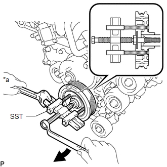
(b) Using the pulley set bolt and SST, remove the crankshaft pulley and pulley bolt.
 Text in Illustration
|
*a |
Hold |
|
|
Turn |
SST: 09950-50013
09951-05010
09952-05010
09953-05020
09954-05031
21. REMOVE NO. 1 FUEL PIPE SUB-ASSEMBLY
22. REMOVE FUEL PUMP ASSEMBLY
23. REMOVE CYLINDER HEAD COVER SUB-ASSEMBLY LH
|
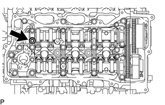
(a) Remove the 2 bolts and 2 VVT sensors from the cylinder head cover sub-assembly LH. |
|
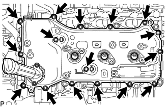
(b) Remove the 14 bolts and cylinder head cover sub-assembly LH from the camshaft housing sub-assembly.
(c) Remove the No. 2 cylinder head cover gasket.
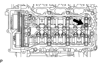
|
(d) Remove the camshaft bearing cap oil hole gasket LH. |
|
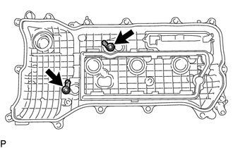
|
(e) Remove the 2 gaskets. |
|
24. REMOVE CYLINDER HEAD COVER SUB-ASSEMBLY
|
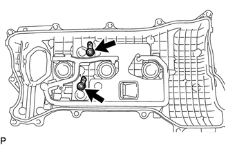
(a) Remove the 2 bolts and 2 VVT sensors from the cylinder head cover sub-assembly. |
|
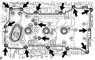
(b) Remove the 13 bolts and cylinder head cover sub-assembly from the camshaft housing sub-assembly.
(c) Remove the cylinder head cover gasket.
|
(d) Remove the camshaft bearing cap oil hole gasket RH. |
|
|
(e) Remove the 2 gaskets. |
|
25. REMOVE SPARK PLUG TUBE GASKET
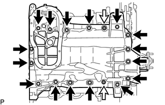
26. REMOVE NO. 2 OIL PAN SUB-ASSEMBLY
(a) Remove the 10 bolts and 2 nuts.
 Text in Illustration
|
|
Bolt |
.png) |
Nut |
|
(b) Insert the blade of an oil pan seal cutter between the oil pans. Cut through the applied sealer and remove the No. 2 oil pan sub-assembly. Text in Illustration
NOTICE: Be careful not to damage the contact surfaces of the oil pans. |
|
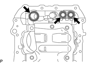
27. REMOVE OIL STRAINER SUB-ASSEMBLY
|
(a) Remove the 2 nuts, oil strainer sub-assembly and O-ring. |
|
28. REMOVE ENGINE OIL LEVEL SENSOR
29. REMOVE OIL PAN SUB-ASSEMBLY
(a) Remove the 16 bolts and 2 nuts.
 Text in Illustration
|
|
Bolt |
|
|
Nut |
HINT:
Make sure the removed parts are returned to the same places they were removed from.
|
(b) Remove the oil pan sub-assembly by prying between the oil pan sub-assembly and cylinder block sub-assembly with a screwdriver. Text in Illustration
NOTICE: Be careful not to damage the contact surfaces of the cylinder block sub-assembly and oil pan sub-assembly. HINT: Tape the screwdriver tip before use. |
|
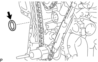
|
(c) Remove the 3 O-rings from the timing chain cover assembly. |
|
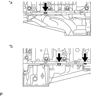
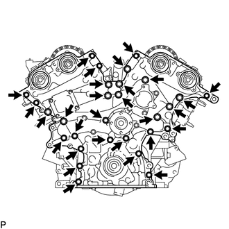
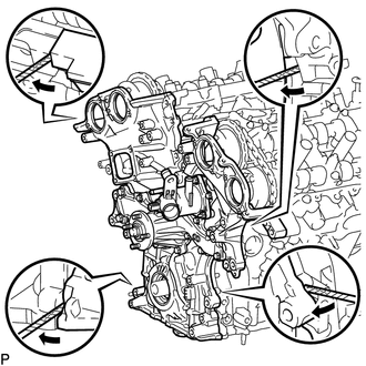
30. REMOVE TIMING CHAIN COVER ASSEMBLY
|
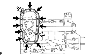
(a) Remove the 27 bolts and 2 nuts. |
|
|
(b) Remove the timing chain cover assembly by prying between the timing chain cover assembly and cylinder head sub-assembly or cylinder block sub-assembly with a screwdriver. NOTICE: Be careful not to damage the contact surfaces of the timing chain cover assembly, cylinder block sub-assembly and cylinder head sub-assembly. HINT: Tape the screwdriver tip before use. |
|
|
(c) Remove the oil pump gasket from the cylinder block sub-assembly. |
|
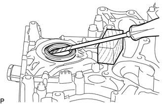
31. REMOVE FRONT CRANKSHAFT OIL SEAL
|
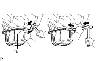
(a) Using a screwdriver and wooden block, pry out the oil seal. NOTICE: Do not damage the surface of the oil seal press fit hole. HINT: Tape the screwdriver tip before use. |
|
 Inspection
INSPECTION
PROCEDURE
1. INSPECT OIL PUMP RELIEF VALVE
(a) Coat the oil pump relief valve with engine oil and check that it
falls smoothly into the valve hole by its own weight.
If ...
 Installation
INSTALLATION
PROCEDURE
1. INSTALL FRONT CRANKSHAFT OIL SEAL
(a) Using SST and a hammer, tap in a new oil seal until its surface is
flush with the timing chain cover assembly edge.
...
Other materials:
System Description
SYSTEM DESCRIPTION
1. GENERAL
This system has the following functions: manual slide open and close; auto slide
open and close; manual tilt up and down; auto tilt up and down; jam protection;
key off operation; key-linked open and close; wireless transmitter-linked open sliding
roof open warn ...
System Diagram
SYSTEM DIAGRAM
Communication Table
Sender ECU
Receiver ECU
Signal
Line
*1: for Vacuum Brake Booster
*2: for Hydraulic Brake Booster
Forward Recognition Camera
Combination Meter Assembly
...
If the vehicle becomes stuck
Carry out the following procedures if the tires spin or the vehicle becomes
stuck in mud, dirt, or snow.
Stop the engine. Set the parking
brake and put the shift lever in P (vehicles with an automatic transmission) or
N (vehicles with a manual transmission).
Remove the mud, snow, or sand f ...
