Toyota Tacoma (2015-2018) Service Manual: Operation Check
OPERATION CHECK
1. OPERATION DESCRIPTION
(a) Push-button start function:
(1) When the electrical key transmitter sub-assembly is in a detection area inside the vehicle and the brake pedal is depressed, the engine is started by pressing the engine switch.
(2) When the electrical key transmitter sub-assembly is in a detection area inside the vehicle and the brake pedal is not depressed, the power source mode is changed by pressing the engine switch. The power source mode changes in the following order every time the engine switch is pressed: off → on (ACC) → on (IG) → off.
(3) After getting into the vehicle while carrying the electrical key transmitter sub-assembly when the engine switch is off, if the engine switch is pressed while not depressing the brake pedal, the power source mode changes to on (ACC) and "ACCESSORY" is displayed on the multi-information display.
 Text in Illustration
|
*a |
"ACCESSORY" Display |
(4) After getting into the vehicle while carrying the electrical key transmitter sub-assembly when the engine switch is off, if the engine switch is pressed 2 times without depressing the brake pedal, the power source mode changes to on (IG) and "IGNITION ON" is displayed on the multi-information display.
 Text in Illustration
|
*a |
"IGNITION ON" Display |
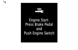
(5) After getting into the vehicle while carrying the electrical key transmitter sub-assembly when the engine switch is off, if the brake pedal is depressed while the shift lever is in P, the entry warning light is displayed on the multi-information display.
 Text in Illustration
|
*a |
Entry Warning Light Displayed |
(6) The engine will start if the engine switch is pressed when the entry warning light is displayed.
(b) Changing the power source mode when the electrical key transmitter sub-assembly does not operate correctly due to wave interference or transmitter battery depletion:
(1) Unlock the door using the built-in mechanical key and get into the vehicle while carrying the electrical key transmitter sub-assembly.
(2) While depressing the brake pedal and facing the logo side of the electrical key transmitter subassembly towards the engine switch, hold the electrical key transmitter sub-assembly near the engine switch.
(3) A buzzer in the combination meter assembly will sound and the power source mode changes to on (IG) and "IGNITION ON" is displayed on the multi-information display.
 Text in Illustration
|
*a |
"IGNITION ON" Display |
(4) Pressing the engine switch without depressing the brake pedal turns the power source mode from on (IG) to off.
(c) Starting the engine when the electrical key transmitter sub-assembly does not operate correctly due to wave interference or transmitter battery depletion:
(1) Unlock the door using the built-in mechanical key and get into the vehicle while carrying the electrical key transmitter sub-assembly.
(2) While depressing the brake pedal with the shift lever in P and facing the logo side of the electrical key transmitter sub-assembly towards the engine switch, hold the electrical key transmitter sub-assembly near the engine switch.
(3) A buzzer in the combination meter assembly will sound, the power source mode changes to on (IG) and the entry warning light will be displayed on the multi-information display.
 Text in Illustration
|
*a |
Entry Warning Light Displayed |
(4) Press the engine switch with the brake pedal depressed to start the engine.
2. CHECK PUSH-BUTTON START FUNCTION
(a) Check the push-button start function:
(1) Get into the vehicle while carrying the electrical key transmitter sub-assembly with the engine switch off. With the shift lever in P, check that the entry warning light is displayed when the brake pedal is depressed. Check that the engine starts when the engine switch is pressed after the entry warning light is displayed on the multi-information display.
 Text in Illustration
|
*a |
Entry Warning Light Displayed |
(2) While the brake pedal is released and the electrical key transmitter sub-assembly is being carried, check that the power source mode changes in the following order when the engine switch is pressed: off → on (ACC) → on (IG) → off.
HINT:
When the engine switch is pressed with the engine switch on (IG) and the shift lever not in P, the power source mode does not change to off, but changes to on (ACC).
(3) With the shift lever in P, check that the steering lock operates when a door is opened.
HINT:
When the engine switch is pressed after the vehicle is stopped, the engine stops and all the power turns off. However, if the shift lever is not in P when the engine switch is pressed with the vehicle stopped, the power source mode does not change to off, but changes to on (ACC).
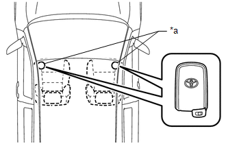
(4) Check the push-button start function operation range for the front side. Place the electrical key transmitter sub-assembly at either inspection point so that it is facing the direction shown in the illustration, and then check that the engine can be started.
 Text in Illustration
|
*a |
Inspection Point |
NOTICE:
- Even if the electrical key transmitter subassembly is in a vehicle interior key detection area, the electrical key transmitter subassembly may not be properly detected if the electrical key transmitter sub-assembly is on the instrument panel, in the glove box or on the floor.
HINT:
- Communication may not be possible if the electrical key transmitter subassembly is within 0.2 m (0.656 ft.) of the center of the rear seat.
- Perform this inspection for both inspection points.
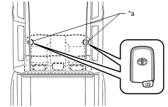
(5) Check the push-button start function operation range for the rear side. Place the electrical key transmitter sub-assembly at either inspection point so that it is facing the direction shown in the illustration, and then check that the engine can be started.
 Text in Illustration
|
*a |
Inspection Point |
NOTICE:
- Even if the electrical key transmitter subassembly is in a vehicle interior key detection area, the electrical key transmitter subassembly may not be properly detected if the electrical key transmitter sub-assembly is on the instrument panel, in the glove box or on the floor.
HINT:
- Communication may not be possible if the electrical key transmitter subassembly is within 0.2 m (0.656 ft.) of the center of the rear seat.
- Perform this inspection for both inspection points.
3. CHECK TRANSMITTER BATTERY SAVING FUNCTION
(a) Check the transmitter battery saving function:
(1) Press the unlock switch of the electrical key transmitter sub-assembly twice while pressing the lock switch and check that the electrical key transmitter sub-assembly LED blinks 4 times and enters transmitter battery saving mode.
(2) Check that the smart key system does not operate while in transmitter battery saving mode.
HINT:
To cancel transmitter battery saving mode, press a switch of the electrical key transmitter subassembly.
4. CHECK POWER SOURCE MODE CHANGING FUNCTION
(a) Check the engine switch.
(1) Check that the power source mode changes according to the chart below.
|
Shift Position |
Brake Pedal |
Power Source Mode when Engine Switch Pressed |
|---|---|---|
|
P |
Released |
Off → on (ACC) → on (IG) → off |
|
P |
Released |
Engine running → off |
|
P |
Released |
On (ACC)*1 → off |
|
P |
Depressed |
Off → engine starts |
|
P |
Depressed |
On (ACC) → engine starts |
|
P |
Depressed |
On (IG) → engine starts |
|
P |
Depressed |
Engine running → off |
|
P |
Depressed |
On (ACC)*1 → off |
|
N |
Released |
Off → on (ACC) → on (IG) (after power source mode changes to on (IG), power source mode changes between on (IG) and on (ACC) every time engine switch is pressed) |
|
N |
Released |
Engine running → on (ACC) |
|
N |
Depressed |
Off → engine starts*2 |
|
N |
Depressed |
On (ACC) → engine starts*2 |
|
N |
Depressed |
On (IG) → engine starts*2 |
|
N |
Depressed |
Engine running → on (ACC) |
|
Not P or N |
Released |
Off → on (ACC) → on (IG) (after power source mode changes to on (IG), power source mode changes between on (IG) and on (ACC) every time engine switch is pressed) |
|
Not P or N |
Released |
Engine running → on (ACC) |
|
Not P or N |
Depressed |
Off → on (IG) |
|
Not P or N |
Depressed |
On (ACC) → on (IG) |
|
Not P or N |
Depressed |
Engine running → on (ACC) |
HINT:
- *1: This situation is only applicable when the power source mode has changed from on (IG) to on (ACC) (Excludes an emergency stop by pressing the engine switch 3 times quickly or pressing and holding the engine switch for 2 seconds or more).
- *2: This situation is only applicable when the steering is unlocked.
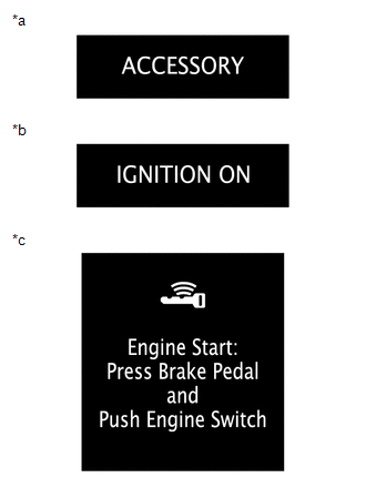
5. CHECK POWER SOURCE MODE INDICATION
(a) Check the entry warning light.
 Text in Illustration
|
*a |
"ACCESSORY" Display |
|
*b |
"IGNITION ON" Display |
|
*c |
Entry Warning Light Display |
|
Power Source Mode |
Multi-information Display |
|---|---|
|
Off (Excluding condition in which the engine can be started) |
Off |
|
On (ACC) (Excluding condition in which the engine can be started) |
"ACCESSORY" displayed |
|
On (IG) (Excluding condition in which the engine can be started) |
"IGNITION ON" displayed |
|
Condition in which engine can be started*1 |
Entry Warning Light displayed |
|
Engine started |
Off |
HINT:
*1: Indicates the conditions in which the engine can be started by pressing the engine switch while either of the following conditions is met:
- Condition 1
All of the following conditions are met:
- The power source mode was turned from on (IG) to on (ACC).
- Key verification is OK*2 or immobiliser is unset (engine switch is on (ACC) or on (IG)).
- The shift lever is in N and the steering is unlocked.
- The stop light switch is on.
- Condition 2
All of the following conditions are met:
- The power source mode was not turned from on (IG) to on (ACC).
- Key verification is OK*2 or immobiliser is unset (engine switch is on (ACC) or on (IG)).
- The stop light switch is on.
- The shift lever is in P, or the shift lever is in N with the steering unlocked.
*2: When the electrical key transmitter sub-assembly is in the cabin, the ID code sent as a result of communication between the electrical key transmitter sub-assembly and certification ECU (smart key ECU assembly) and the ID code calculated by the certification ECU (smart key ECU assembly) are compared. If the ID codes match each other, the vehicle recognizes that the electrical key transmitter sub-assembly is in the cabin.
 How To Proceed With Troubleshooting
CAUTION / NOTICE / HINT
HINT:
Use these procedures to troubleshoot the smart key system (for Start
Function).
*: Use the Techstream.
PROCEDURE
1.
VEHIC ...
 System Description
SYSTEM DESCRIPTION
1. SYSTEM FUNCTION
Function
Outline
Push-button start function
When the key is brought into the vehicle and verified, this functi ...
Other materials:
Disassembly
DISASSEMBLY
CAUTION / NOTICE / HINT
HINT:
The procedure described below is for the LH side. Use the same procedure for
both the LH and RH sides, unless otherwise specified.
PROCEDURE
1. REMOVE REAR SEATBACK COVER
(a) Remove the 2 screws.
...
Input/Turbine Speed Sensor "A" Circuit Short to Battery (P071512,P071514,P071531)
DESCRIPTION
This sensor detects the rotation speed of the turbine which shows the input turbine
speed of the transmission. By comparing the input turbine speed signal (NT) with
the output shaft speed sensor signal (SP2), the ECM detects the shift timing of
the gears and appropriately controls ...
Certification ECU Communication Stop Mode
DESCRIPTION
Detection Item
Symptom
Trouble Area
Certification ECU Communication Stop Mode
Either condition is met:
Communication stop for "Certification (Smart)" is indicated
on the "Communication Bus Ch ...
