Toyota Tacoma (2015-2018) Service Manual: Ambient Temperature Sensor Circuit (B1412)
DESCRIPTION
The ambient temperature sensor is installed in front of the condenser to detect the ambient temperature which is used to control the air conditioning system AUTO mode. This sensor is connected to the air conditioning amplifier assembly and detects fluctuations in the ambient temperature. This data is used for controlling the cabin temperature. The sensor sends a signal to the air conditioning amplifier assembly. The resistance of the ambient temperature sensor changes in accordance with the ambient temperature. As the temperature decreases, the resistance increases. As the temperature increases, the resistance decreases.
The air conditioning amplifier assembly applies a voltage (5 V) to the ambient temperature sensor and reads voltage changes due to changes in the resistance of the ambient temperature sensor.
|
DTC No. |
DTC Detection Condition |
Trouble Area |
|---|---|---|
|
B1412 |
Open or short in cooler thermistor (ambient temperature sensor) circuit |
|
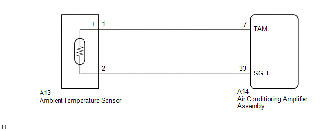
WIRING DIAGRAM
PROCEDURE
|
1. |
READ VALUE USING TECHSTREAM |
(a) Connect the Techstream to the DLC3.
(b) Turn the ignition switch to ON.
(c) Turn the Techstream on.
(d) Enter the following menus: Body Electrical / Air Conditioner / Data List.
(e) Check the value(s) by referring to the table below.
Air Conditioner|
Tester Display |
Measurement Item/Range |
Normal Condition |
Diagnostic Note |
|---|---|---|---|
|
Ambient Temp Sensor |
Ambient temperature sensor / Min: -23.30°C (-9.94°F) Max: 65.95°C (150.71°F) |
Actual ambient temperature displayed |
- |
OK:
The display is as specified in the Normal Condition column.
|
Result |
Proceed to |
|---|---|
|
NG |
A |
|
OK (When troubleshooting according to Problem Symptoms Table) |
B |
|
OK (When troubleshooting according to the DTC) |
C |
| B | .gif) |
PROCEED TO NEXT SUSPECTED AREA SHOWN IN PROBLEM SYMPTOMS TABLE |
| C | |
REPLACE AIR CONDITIONING AMPLIFIER ASSEMBLY |
|
.gif)
|
2. |
INSPECT AMBIENT TEMPERATURE SENSOR |
(a) Remove the ambient temperature sensor (See page
.gif) ).
).
(b) Inspect the ambient temperature sensor (See page
).
| NG | |
REPLACE AMBIENT TEMPERATURE SENSOR |
|
|
3. |
CHECK HARNESS AND CONNECTOR (AMBIENT TEMPERATURE SENSOR - AIR CONDITIONING AMPLIFIER ASSEMBLY) |
(a) Disconnect the A13 ambient temperature sensor connector.
(b) Disconnect the A14 air conditioning amplifier assembly connector.
(c) Measure the resistance according to the value(s) in the table below.
Standard Resistance:
|
Tester Connection |
Condition |
Specified Condition |
|---|---|---|
|
A14-7 (TAM) - A13-1 (+) |
Always |
Below 1 Ω |
|
A14-33 (SG-1) - A13-2 (-) |
Always |
Below 1 Ω |
|
A14-7 (TAM) or A13-1 (+) - Body ground |
Always |
10 kΩ or higher |
|
A14-33 (SG-1) or A13-2 (-) - Body ground |
Always |
10 kΩ or higher |
| OK | |
REPLACE AIR CONDITIONING AMPLIFIER ASSEMBLY |
| NG | |
REPAIR OR REPLACE HARNESS OR CONNECTOR |
 Diagnostic Trouble Code Chart
DIAGNOSTIC TROUBLE CODE CHART
Air Conditioning System
DTC Code
Detection Item
Memory
See page
B1412
Ambient Temperature Sensor ...
 Pressure Sensor Circuit (B1423)
DESCRIPTION
This DTC is stored if refrigerant pressure on the high pressure side is extremely
low (176 kPa (1.8 kgf/cm2, 26 psi) or less) or extremely high (3140 kPa (32.0 kgf/cm2,
455 psi) or mo ...
Other materials:
Heater Relay
Inspection
INSPECTION
PROCEDURE
1. INSPECT HEATER RELAY
(a) Check the resistance.
(1) Using an ohmmeter, measure the resistance between each terminal.
Standard:
Tester Connection
Specified Condition
3 - 4
...
Skid Control Buzzer Circuit (C1A4A)
DESCRIPTION
Based on dynamic radar cruise control system operation, the forward recognition
camera provides warnings to the driver by sounding the skid control buzzer.
DTC C1A4A is stored when a malfunction is detected in the skid control buzzer
circuit.
DTC No.
Detectio ...
Heater Circuit (C1AAE)
DESCRIPTION
If the forward recognition camera detects a malfunction in the camera heater
(forward recognition hood) circuit, it will output a malfunction signal to the millimeter
wave radar sensor assembly via CAN communication and DTC C1AAE will be stored.
DTC No.
Detect ...
