Toyota Tacoma (2015-2018) Service Manual: Components
COMPONENTS
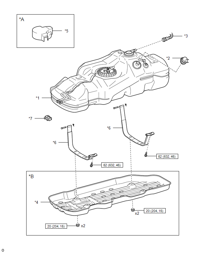
ILLUSTRATION
|
*A |
w/ Fuel Tank Cover |
*B |
for Hydraulic Brake Booster |
|
*1 |
FUEL TANK ASSEMBLY |
*2 |
FUEL TANK INLET PIPE SUB-ASSEMBLY |
|
*3 |
FUEL TANK VENT HOSE SUB-ASSEMBLY |
*4 |
NO. 1 FUEL TANK PROTECTOR SUB-ASSEMBLY |
|
*5 |
FUEL TANK COVER |
*6 |
FUEL TANK BAND |
|
*7 |
FUEL PIPE CLAMP |
- |
- |
.png) |
N*m (kgf*cm, ft.*lbf): Specified torque |
- |
- |
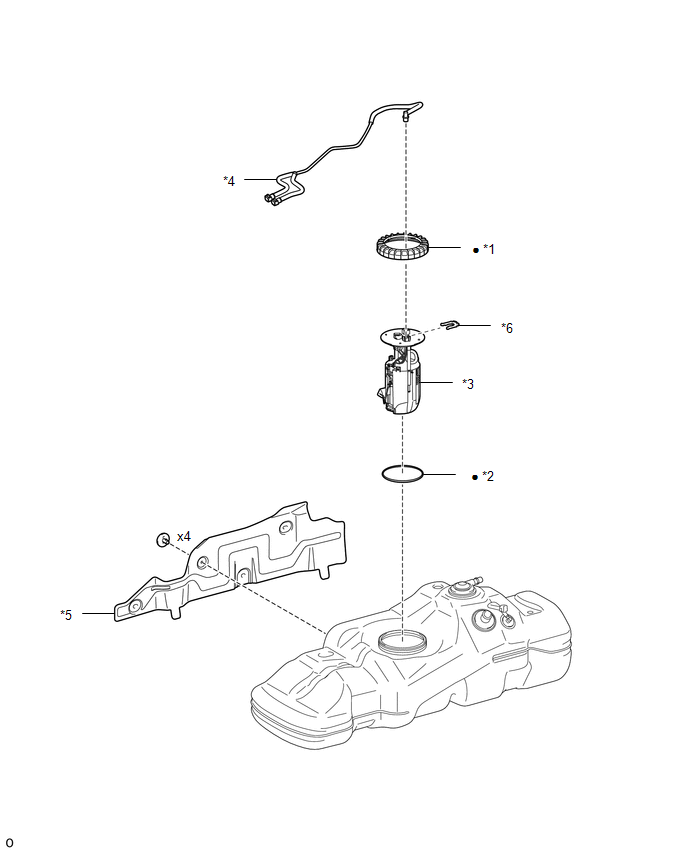
ILLUSTRATION
|
*1 |
FUEL PUMP GAUGE RETAINER |
*2 |
FUEL SUCTION TUBE SET GASKET |
|
*3 |
FUEL SUCTION TUBE WITH PUMP AND GAUGE ASSEMBLY |
*4 |
FUEL TANK MAIN TUBE SUB-ASSEMBLY |
|
*5 |
NO. 1 FUEL TANK PROTECTOR |
*6 |
TUBE JOINT CLIP |
|
â—Ź |
Non-reusable part |
- |
- |
 Fuel Tank
...
 Removal
REMOVAL
PROCEDURE
1. PRECAUTION
NOTICE:
After turning the ignition switch off, waiting time may be required before disconnecting
the cable from the battery terminal. Therefore, make sure to read ...
Other materials:
Jam Protection Function does not Operate
DESCRIPTION
This symptom may occur for any of the windows.
The jam protection function operates within a specified range during the manual
up or auto up operation.
CAUTION / NOTICE / HINT
NOTICE:
If a power window regulator motor assembly has been replaced with a
new one, initiali ...
Installation
INSTALLATION
PROCEDURE
1. INSTALL FRONT AXLE HUB
2. INSTALL FRONT SUSPENSION UPPER ARM
(a) Install a new nut and clip.
Torque:
110 N·m {1122 kgf·cm, 81 ft·lbf}
3. INSTALL FRONT SUSPENSION LOWER ARM
(a) Install the front suspension lower arm with the 2 bolts.
Torque:
160 N·m {1631 ...
Open or Short Circuit in Back Camera Signal (C1622)
DESCRIPTION
This DTC is stored if the radio and display receiver assembly*1 or navigation
receiver assembly*2 judges as a result of its self check that the signals or signal
lines between the radio and display receiver assembly*1 or navigation receiver assembly*2
and the rear television camer ...
