Toyota Tacoma (2015-2018) Service Manual: Traction Off Switch
Components
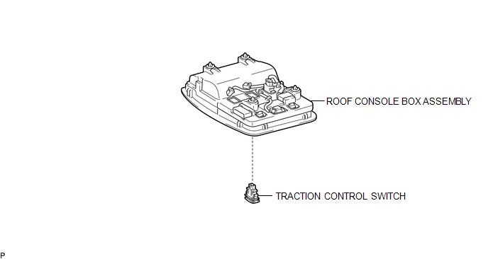
COMPONENTS
ILLUSTRATION
Removal
REMOVAL
PROCEDURE
1. REMOVE ROOF CONSOLE BOX ASSEMBLY
(See page .gif) )
)
2. REMOVE A-TRAC SWITCH (TRACTION CONTROL SWITCH)
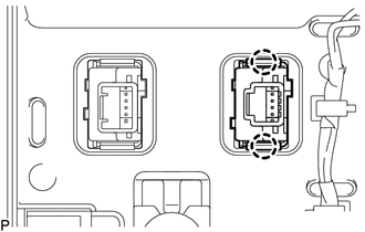
(a) Disconnect the A-TRAC switch (traction control switch) connector.
|
(b) Using a screwdriver, detach the 2 claws and remove the A-TRAC switch (traction control switch) from the roof console box assembly. |
|
Inspection
INSPECTION
PROCEDURE
1. INSPECT A-TRAC SWITCH (TRACTION CONTROL SWITCH)
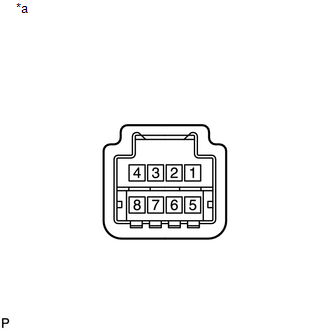
(a) Check the resistance.
|
(1) Measure the resistance according to the value(s) in the table below. Text in Illustration
Standard Resistance:
If the value is not as specified, replace the A-TRAC switch (traction control switch). |
|
Installation
INSTALLATION
PROCEDURE
1. INSTALL A-TRAC SWITCH (TRACTION CONTROL SWITCH)
(a) Attach the 2 claws to install the A-TRAC switch (traction control switch) into the roof console box assembly.
(b) Connect the A-TRAC switch (traction control switch) connector.
2. INSTALL ROOF CONSOLE BOX ASSEMBLY
(See page .gif) )
)
 Removal
REMOVAL
PROCEDURE
1. REMOVE STEERING PAD
(See page )
2. REMOVE STEERING WHEEL ASSEMBLY
3. REMOVE LOWER STEERING COLUMN COVER
4. REMOVE UPPER STEERING COLUMN COVER
5. REMOVE SPIRAL ...

Other materials:
Using the AUX port
To use the AUX port, connect a portable player, then select “AUX” on the “Select
Audio Source” screen.
Connecting a portable audio player
■Operating portable audio players connected to the multimedia system
The volume can be adjusted using the vehicle’s audio controls. All other ...
Brake Switch "A" Circuit Open (P057113)
DESCRIPTION
DTC No.
DTC Detection Condition
Trouble Area
MIL
Note
P057113
Vehicle Condition:
Cruise control operating
Malfunction Status:
Stop light switch assembly circuit malfunction ...
Cleaning and protecting the vehicle interior
The following procedures will help protect your vehicle’s interior and keep
it in top condition:
■ Protecting the vehicle interior
Remove dirt and dust using a vacuum cleaner. Wipe dirty surfaces with a cloth
dampened with lukewarm water.
■ Cleaning the leather areas
● Re ...
