Toyota Tacoma (2015-2018) Service Manual: Removal
REMOVAL
PROCEDURE
1. REMOVE FRONT PILLAR GARNISH LH
(See page .gif) )
)
2. REMOVE ASSIST GRIP SUB-ASSEMBLY
(See page )
3. REMOVE FRONT PILLAR GARNISH RH
(See page )
4. REMOVE NO. 1 INSTRUMENT PANEL SPEAKER PANEL SUB-ASSEMBLY
(See page )
5. REMOVE NO. 2 INSTRUMENT PANEL SPEAKER PANEL SUB-ASSEMBLY
(See page )
6. REMOVE FRONT NO. 2 SPEAKER ASSEMBLY LH
(a) Remove the 2 bolts.
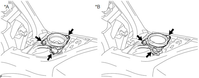 Text in Illustration
|
*A |
w/o Amplifier Box Speaker Assembly |
*B |
w/ Amplifier Box Speaker Assembly |
(b) Disconnect the connector to remove the front No. 2 speaker assembly LH.
NOTICE:
Do not touch the cone part of the front No. 2 speaker assembly LH.
7. REMOVE FRONT NO. 2 SPEAKER ASSEMBLY RH
(a) Remove the 2 bolts.
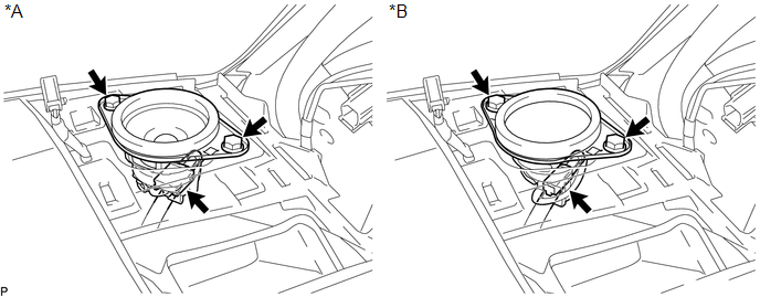 Text in Illustration
|
*A |
w/o Amplifier Box Speaker Assembly |
*B |
w/ Amplifier Box Speaker Assembly |
(b) Disconnect the connector to remove the front No. 2 speaker assembly RH.
NOTICE:
Do not touch the cone part of the front No. 2 speaker assembly RH.
 Components
COMPONENTS
ILLUSTRATION
ILLUSTRATION
...
 Inspection
INSPECTION
PROCEDURE
1. INSPECT FRONT NO. 2 SPEAKER ASSEMBLY
(a) When there is a malfunction such as noise from a speaker or no sound at all,
replace the speaker with a new one and check that the ...
Other materials:
Removal
REMOVAL
PROCEDURE
1. PRECAUTION
NOTICE:
After turning the ignition switch off, waiting time may be required before disconnecting
the cable from the battery terminal. Therefore, make sure to read the disconnecting
the cable from the battery terminal notice before proceeding with work.
Click ...
Customize Parameters
CUSTOMIZE PARAMETERS
1. CUSTOMIZING FUNCTION WITH TECHSTREAM
NOTICE:
When the customer requests a change in a function, first make sure that
the function can be customized.
Be sure to make a note of the current settings before customizing.
When troubleshooting a function, f ...
Diagnosis System
DIAGNOSIS SYSTEM
CHECK DLC3
(a) Check the DLC3.
Click here
FUNCTION OF WARNING INDICATOR AND MESSAGE
(a) If the pre-collision system is not functioning properly, the driver is warned
by the PCS warning light and a warning message displayed on the multi-information
display.
Mas ...
