Toyota Tacoma (2015-2018) Service Manual: Components
COMPONENTS
ILLUSTRATION
ILLUSTRATION

 Removal
REMOVAL
PROCEDURE
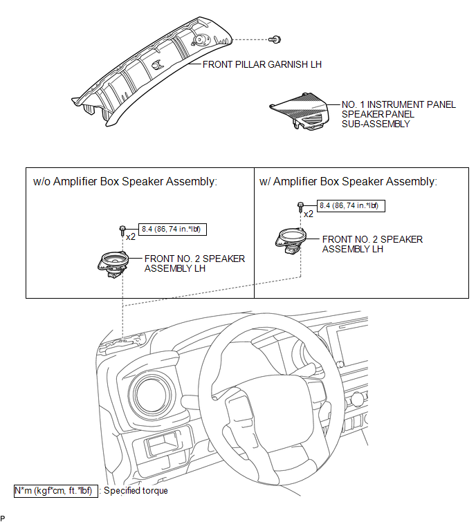
1. REMOVE FRONT PILLAR GARNISH LH
(See page )
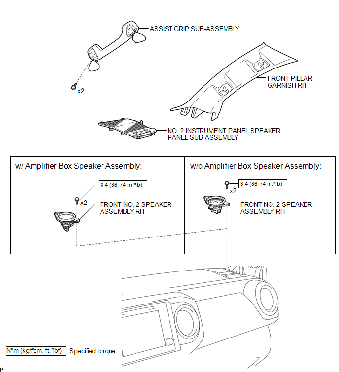
2. REMOVE ASSIST GRIP SUB-ASSEMBLY
(See page )
3. REMOVE FRONT PILLAR GARNISH RH
(See page )
4. REMOVE NO. 1 INSTRUMENT PA ...
Other materials:
Ignition Switch
Components
COMPONENTS
ILLUSTRATION
Removal
REMOVAL
PROCEDURE
1. REMOVE LOWER STEERING COLUMN COVER
(a) Remove the 2 screws.
(b) Disengage the 2 claws and remove the lower steering column cover.
2. REMOVE IGNITION OR STARTER SWITCH ASSEMBLY
(a) Disconnect the connector.
(b) Disen ...
Diagnostic Trouble Code Chart
DIAGNOSTIC TROUBLE CODE CHART
Sliding Roof (Sliding Roof ECU (Sliding Roof Drive Gear Sub-assembly))
DTC Code
Detection Item
See page
B2341
Sensor (Motor) Failure
B2342
Switch Failure
...
Terminals Of Ecu
TERMINALS OF ECU
1. OCCUPANT DETECTION ECU
Symbols (Terminal No.)
Wiring Color
Terminal Description
Condition
Specification
+B (O5-1) -
GND (O5-3)
R - W-B
Battery
Ignition switch on
...
