Toyota Tacoma (2015-2018) Service Manual: Removal
REMOVAL
PROCEDURE
1. REMOVE REAR SEAT ASSEMBLY LH (for Double Cab)
Click here .gif)
2. REMOVE REAR SEAT ASSEMBLY RH (for Double Cab)
Click here
3. REMOVE REAR DOOR SCUFF PLATE LH (for Double Cab)
Click here
4. REMOVE REAR DOOR SCUFF PLATE RH (for Double Cab)
HINT:
Use the same procedure as for the LH side.
5. DISCONNECT REAR DOOR OPENING TRIM WEATHERSTRIP LH (for Double Cab)
Click here
6. DISCONNECT REAR DOOR OPENING TRIM WEATHERSTRIP RH (for Double Cab)
HINT:
Use the same procedure as for the LH side.
7. REMOVE LUGGAGE COMPARTMENT SIDE TRAY RH (for Double Cab)
- w/ Woofer:
Click here
- w/o Woofer:
Click here
8. REMOVE QUARTER TRIM LOWER PANEL LH (for Double Cab)
Click here
9. REMOVE QUARTER TRIM LOWER PANEL RH (for Double Cab)
HINT:
Use the same procedure as for the LH side.
10. REMOVE QUARTER INSIDE TRIM BOARD LH (for Access Cab)
Click here
11. REMOVE QUARTER INSIDE TRIM BOARD LH (for Double Cab)
Click here
12. REMOVE QUARTER INSIDE TRIM BOARD RH (for Access Cab)
HINT:
Use the same procedure as for the LH side.
13. REMOVE QUARTER INSIDE TRIM BOARD RH (for Double Cab)
HINT:
Use the same procedure as for the LH side.
14. REMOVE ASSIST GRIP SUB-ASSEMBLY (for Double Cab)
Click here
15. REMOVE ASSIST GRIP PLUG (for Access Cab)
Click here
16. REMOVE COAT HOOK
Click here
17. REMOVE NO. 1 BACK PANEL SILENCER (for Power Slide Type)
|
(a) Using a clip remover, remove the 6 clips and No. 1 back panel silencer. |
|
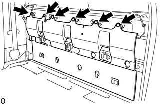
18. REMOVE DOOR WINDOW REGULATOR CABLE SUB-ASSEMBLY (for Power Slide Type)
(a) Using a clip remover, disengage the 5 clips labeled A in the illustration.
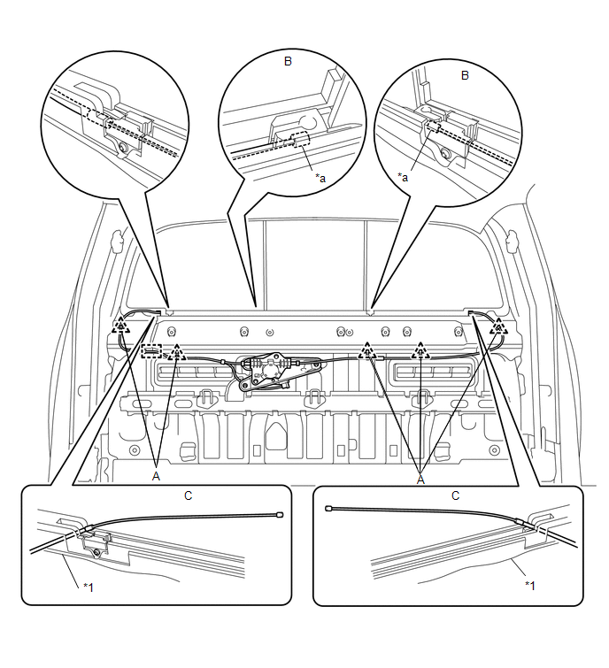
|
*1 |
Back Window Assembly |
- |
- |
|
*a |
Wire End |
- |
- |
(b) Disengage the clamp.
(c) Compress the springs to release the tension in the cables, and then disconnect the wire ends from the back window assembly as shown in the illustration labeled B.
(d) Pull out the cables from the back window assembly as shown in the illustration labeled C.
|
(e) Disconnect the connector. |
|
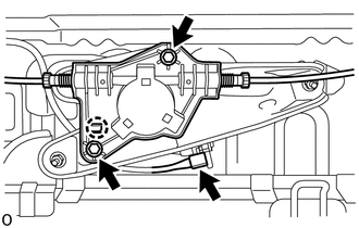
(f) Remove the 2 bolts.
(g) Disengage the claw to remove the door window regulator cable sub-assembly.
19. REMOVE DOOR WINDOW REGULATOR BASE PLATE (for Power Slide Type)
|
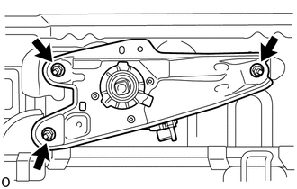
(a) Remove the 3 nuts and door window regulator base plate. |
|
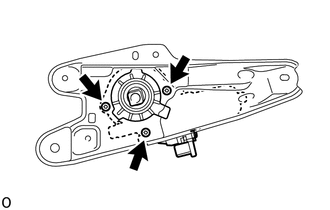
20. REMOVE POWER WINDOW REGULATOR MOTOR ASSEMBLY (for Power Slide Type)
|
(a) Using a T25 "TORX" socket, remove the 3 screws and power window regulator motor assembly. |
|
21. REMOVE BACK WINDOW SLIDE GLASS SUB-ASSEMBLY (for Power Slide Type)
HINT:
Perform these procedures only when replacing the back window slide glass sub-assembly.
(a) Using a T10 "TORX" driver, remove the screw and stopper (illustration A).

|
*1 |
Back Window Slide Glass Sub-assembly |
*2 |
Seal |
|
*3 |
Stopper |
- |
- |
(b) Slightly pull up the seal (arrow 1), and then pull out the seal from the channel in the direction of arrow 2.
(c) Slide the back window slide glass sub-assembly towards the LH side (arrow 3). Lower the back window slide glass sub-assembly into the channel and tilt it (arrow 4) to disengage the upper part of the back window slide glass sub-assembly from the upper channel. Then remove the back window slide glass sub-assembly (arrow 5).
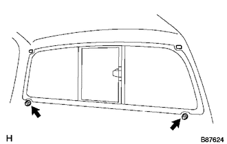
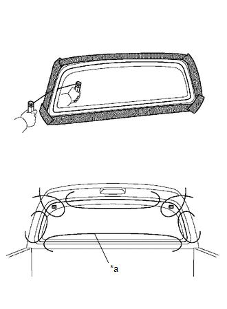
22. REMOVE BACK WINDOW ASSEMBLY
NOTICE:
The back window assembly may fall while performing this procedure. Therefore, use suction cups to hold the back window assembly from the outside of the vehicle.
|
(a) Remove the 2 nuts. |
|
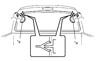
(b) Apply protective tape to the area around the installation position of the back window assembly on the vehicle body to prevent it from being scratched.
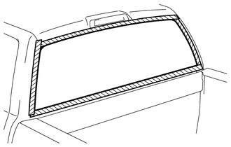
.png) |
Protective Tape |
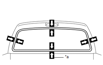
(c) When reusing the back window assembly:
|
(1) Place matchmarks on the back window assembly and vehicle body at the locations indicated in the illustration. |
|
(d) Install the suction cups to the back window assembly.
|
(e) Pass a piano wire between the vehicle body and back window assembly from the interior. |
|
(f) Tie both wire ends to wooden blocks or similar objects that can serve as handles.
(g) Cut off the adhesive by pulling the piano wire around the back window assembly.
NOTICE:
Do not forcefully brush the piano wire against the back window assembly.
|
(h) Using suction cups, disengage the 2 clips to remove the back window assembly. |
|
 Inspection
INSPECTION
PROCEDURE
1. INSPECT POWER WINDOW REGULATOR MOTOR ASSEMBLY (for Power Slide Type)
*a
Component without harness connected
(Power Window Regulator Motor Assembly ...

Other materials:
PTC Heater Circuit
DESCRIPTION
PTC HTR heater relays are closed in accordance with signals from the air conditioning
amplifier assembly and power is supplied to the quick heater assembly installed
on the radiator heater unit.
WIRING DIAGRAM
CAUTION / NOTICE / HINT
NOTICE:
Inspect the fuses for circuits rela ...
Removal
REMOVAL
PROCEDURE
1. REMOVE LOWER STEERING COLUMN COVER
2. REMOVE UPPER STEERING COLUMN COVER
3. REMOVE WINDSHIELD WIPER SWITCH ASSEMBLY
(a) Disconnect the 2 connectors.
Text in Illustration
*a
Protective Tape
...
Acceleration Sensor Malfunction (C1420)
DESCRIPTION
Refer to DTCs C1419 and C1435 (See page ).
DTC Code
DTC Detection Condition
Trouble Area
C1420
After the difference between GL1 and GL2 becomes 0.6 G or more with the
vehicle stationary, the difference remains 0.4 G or m ...
