Toyota Tacoma (2015-2018) Service Manual: Removal
REMOVAL
CAUTION / NOTICE / HINT
HINT:
If the bumper is damaged, there is a possibility that the installation area of the blind spot monitor sensor may be deformed and the blind spot monitor system may not operate correctly, so visually inspect the blind spot monitor sensor installation area (frame, stud bolt) to make sure it is not dented or bent.
Click here .gif)
If the visual inspection finds a problem, check the installation condition of the blind spot monitor sensor, and adjust the installation position of the blind spot monitor sensor as necessary.
PROCEDURE
1. REMOVE REAR BUMPER ASSEMBLY
|
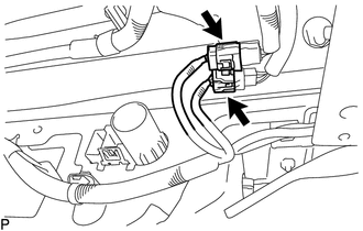
(a) Disconnect the 2 connectors. |
|
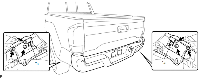
(b) Using an engine lifter or equivalent, remove the 6 bolts.
 Text in Illustration
|
*a |
Pin |
- |
- |
(c) Disengage the 2 pins to remove the rear bumper assembly.
NOTICE:
- Using plate lift attachments or equivalent, set the rear bumper assembly on a flat surface.
- Be sure to perform the operation with 2 persons or more.
- Be careful not to damage the rear bumper assembly.
 Components
COMPONENTS
ILLUSTRATION
ILLUSTRATION
ILLUSTRATION
ILLUSTRATION
...
 Disassembly
DISASSEMBLY
PROCEDURE
1. REMOVE REAR BUMPER HOLE COVER
(a) Disengage the 2 clips to remove the rear bumper hole cover.
2. REMOVE REAR BUMPER PA ...
Other materials:
Problem Symptoms Table
PROBLEM SYMPTOMS TABLE
HINT:
Use the table below to help determine the cause of problem symptoms. If multiple
suspected areas are listed, the potential causes of the symptoms are listed in order
of probability in the "Suspected Area" column of the table. Check each symptom by
check ...
Components
COMPONENTS
ILLUSTRATION
HINT:
The following specifications are for BD20D (w/o Differential Lock). BD20D differentials
are equipped with M8 rear differential carrier to rear axel housing fasteners.
ILLUSTRATION
ILLUSTRATION
...
Symbols used in illustrations
The symbol of a circle with a slash
through it means тАЬDo notтАЭ, тАЬDo not do thisтАЭ, or тАЬDo not let this happenтАЭ.
Arrows indicating operations
Indicates the action (pushing, turning,
etc.) used to operate switches and other devices.
Indicates the outcome of an operation
(e.g. a ...
