Toyota Tacoma (2015-2018) Service Manual: Inspection
INSPECTION
PROCEDURE
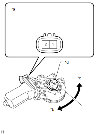
1. INSPECT POWER WINDOW REGULATOR MOTOR ASSEMBLY (for Power Slide Type)
|
*a |
Component without harness connected (Power Window Regulator Motor Assembly) |
|
*b |
Clockwise |
|
*c |
Counterclockwise |
|
*d |
Motor Gear |
(a) Check the operation of the power window regulator motor assembly.
(1) Apply battery voltage to the power window regulator motor assembly.
(2) Check that the motor gear rotates smoothly as follows.
OK:
|
Measurement Condition |
Specified Condition |
|---|---|
|
Battery positive (+) → 2 Battery negative (-) → 1 |
Motor gear rotates clockwise |
|
Battery positive (+) → 1 Battery negative (-) → 2 |
Motor gear rotates counterclockwise |
If the result is not as specified, replace the power window regulator motor assembly.
2. INSPECT NO. 1 POWER WINDOW RELAY
(a) Check the resistance.
|
(1) Measure the resistance according to the value(s) in the table below. Standard resistance:
If the result is not as specified, replace the No. 1 power window relay. |
|
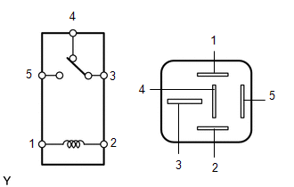
3. INSPECT NO. 2 POWER WINDOW RELAY
(a) Check the resistance.
|
(1) Measure the resistance according to the value(s) in the table below. Standard resistance:
If the result is not as specified, replace the No. 2 power window relay. |
|
 Components
COMPONENTS
ILLUSTRATION
*A
for Double Cab
*B
w/o Woofer
*C
w/ Woofer
-
-
*1
...
 Removal
REMOVAL
PROCEDURE
1. REMOVE REAR SEAT ASSEMBLY LH (for Double Cab)
Click here
2. REMOVE REAR SEAT ASSEMBLY RH (for Double Cab)
Click here
3. REMOVE REAR DOOR SCUFF PLATE LH (for Double Cab)
...
Other materials:
Power Source Control ECU Malfunction (B2782)
DESCRIPTION
DESCRIPTION The certification ECU (smart key ECU assembly) has a power source
mode switching function.
This DTC is stored when the IGE input (the steering lock motor activation permission
signal) sent directly from the certification ECU (smart key ECU assembly) to the
steering lo ...
Cruise Main Indicator Light Circuit
DESCRIPTION
When the ECM detects a cruise control switch on signal from the cruise
control switch, the ECM sends the signal to the combination meter assembly
through CAN communication. Then the cruise control indicator light turns
on.
The cruise control indicator light circui ...
Open in Stop Light Switch Circuit (C1425)
DESCRIPTION
The skid control ECU (brake actuator assembly) detects the brake operating conditions
through a signal transmitted by the stop light switch.
The skid control ECU incorporates a circuit to detect an open circuit. This DTC
is output when an open circuit is detected in the stop light ...
