Toyota Tacoma (2015-2018) Service Manual: Removal
REMOVAL
CAUTION / NOTICE / HINT
HINT:
- Use the same procedure for both the RH and LH sides.
- The procedure described below is for the LH side.
PROCEDURE
1. PRECAUTION
CAUTION:
Be sure to read Precaution thoroughly before servicing (See page
.gif) ).
).
NOTICE:
After turning the ignition switch off, waiting time may be required before disconnecting the cable from the negative (-) battery terminal. Therefore, make sure to read the disconnecting the cable from the negative (-) battery terminal notices before proceeding with work.
Click here
2. DISCONNECT CABLE FROM NEGATIVE BATTERY TERMINAL
Wait for at least 90 seconds after disconnecting the cable to prevent the airbag from working.
NOTICE:
When disconnecting the cable, some systems need to be initialized after the cable is reconnected.
Click here
3. REMOVE FRONT DOOR SCUFF PLATE
4. REMOVE REAR DOOR SCUFF PLATE
5. DISCONNECT FRONT DOOR OPENING TRIM WEATHERSTRIP
6. DISCONNECT REAR DOOR OPENING TRIM WEATHERSTRIP
7. REMOVE LAP BELT OUTER ANCHOR COVER
8. REMOVE CENTER PILLAR LOWER GARNISH
9. REMOVE SIDE AIRBAG SENSOR ASSEMBLY
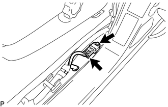
(a) Disconnect the connector from the side airbag sensor.
NOTICE:
When disconnecting any airbag connector, take care not to damage the airbag wire harness.
(1) Push and hold the white housing lock, and slide the yellow outer connector locking sleeve.
.png)
(2) Push and hold the white housing lock again, and slide the yellow outer connector locking sleeve to disconnect the connector.
(b) Remove the bolt and side airbag sensor.
NOTICE:
Loosen the bolt while holding the door side airbag sensor because the side airbag sensor pin (stopper) is easily damaged.
 On-vehicle Inspection
ON-VEHICLE INSPECTION
PROCEDURE
1. INSPECT SIDE AIRBAG SENSOR ASSEMBLY (for Vehicle not Involved in Collision)
(a) Perform a diagnostic system check (See page
).
2. INSPECT SIDE AIRBAG SENSOR AS ...
 Spiral Cable
...
Other materials:
Components
COMPONENTS
ILLUSTRATION
ILLUSTRATION
ILLUSTRATION
ILLUSTRATION
ILLUSTRATION
*A
w/ Seat Heater System
-
-
*1
FRONT SEAT CUSHION HEATER ASSEMBLY
*2
FRONT SEATBACK HEATER ASSEMBLY
...
Reassembly
REASSEMBLY
PROCEDURE
1. INSTALL NO. 2 ANTENNA CORD SUB-ASSEMBLY
(a) Using hot-melt glue, install the No. 2 antenna cord sub-assembly as shown
in the illustration.
2. INSTALL NO. 1 ROOF WIRE (w/ Vanity Light)
(a) w/ EC Mirror:
(1) Align the aiming tape as shown in the illustration.
...
Inspection
INSPECTION
PROCEDURE
1. INSPECT PARK/NEUTRAL POSITION SWITCH
(a) Measure the resistance according to the value(s) in the table below.
Text in Illustration
*a
Component without harness connected
(Park/Neutral Position Switch)
...
