Toyota Tacoma (2015-2018) Service Manual: Removal
REMOVAL
PROCEDURE
1. REMOVE REAR SEATBACK HINGE COVER
.gif)
2. REMOVE REAR SEATBACK ASSEMBLY
3. REMOVE REAR SEATBACK HINGE SUB-ASSEMBLY
4. REMOVE REAR DOOR SCUFF PLATE
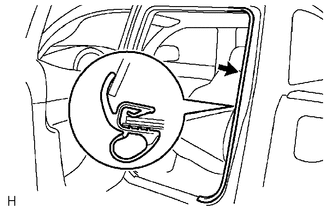
5. DISCONNECT REAR DOOR OPENING TRIM WEATHERSTRIP
|
(a) Disconnect the rear door opening trim weatherstrip to the extent which allows the removal of the quarter trim lower panel and quarter inside trim board. |
|
6. REMOVE LUGGAGE COMPARTMENT SIDE TRAY
7. REMOVE QUARTER TRIM LOWER PANEL
8. DISCONNECT REAR SEAT 3 POINT TYPE OUTER BELT ASSEMBLY
9. REMOVE QUARTER INSIDE TRIM BOARD
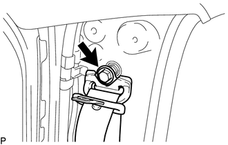
10. REMOVE REAR SEAT 3 POINT TYPE OUTER BELT ASSEMBLY
|
(a) Loosen the bolt to disconnect the shoulder anchor. |
|
|
(b) Remove the 2 bolts. |
|
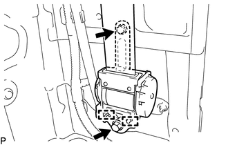
(c) Disengage the 2 guides to remove the rear seat 3 point type outer belt assembly.
 Installation
INSTALLATION
PROCEDURE
1. INSTALL REAR SEAT 3 POINT TYPE OUTER BELT ASSEMBLY
(a) Before installing the rear seat 3 point type outer belt assembly,
check the ELR function.
Text in ...

Other materials:
Rear Speed Sensor RH Performance (C1411,C1412)
DESCRIPTION
Refer to DTCs C1401 and C1402 (See page ).
DTC Code
DTC Detection Condition
Trouble Area
C1411
C1412
One of the following conditions is met:
When the vehicle is driven in reverse at a speed of 3 km/h (2
...
Vehicle Speed Sensor "A" No Signal (P050031)
DESCRIPTION
Vehicles, which are equipped with ABS (Anti-lock Brake System), detect the vehicle
speed using the skid control ECU (brake actuator assembly) and speed sensors. Each
speed sensor monitors the wheel rotation speed and sends a signal to the skid control
ECU. The skid control ECU con ...
Installation of a mobile two-way radio system
The installation of a mobile two-way radio system in your vehicle could affect
electronic systems such as: ● Multiport fuel injection system/sequential multiport
fuel injection system
● Cruise control system
● Anti-lock brake system
● SRS airbag system
● Seat be ...
