Toyota Tacoma (2015-2018) Service Manual: Inspection
INSPECTION
PROCEDURE
1. INSPECT PROPELLER SHAFT WITH CENTER BEARING ASSEMBLY
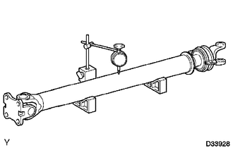
(a) Using a dial indicator, check the propeller shaft runout.
Maximum runout:
0.6 mm (0.0236 in.)
If the shaft runout is greater than the maximum, replace the shaft.
2. INSPECT PROPELLER SHAFT
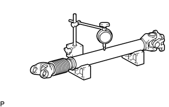
(a) Using a dial indicator, check the propeller shaft runout.
Maximum runout:
0.6 mm (0.0236 in.)
If the shaft runout is greater than the maximum, replace the shaft.
 Disassembly
DISASSEMBLY
PROCEDURE
1. REMOVE REAR PROPELLER SHAFT BOOT CLAMP
(a) Place matchmarks on the propeller shaft and sleeve yoke.
Text in Illustration
*1
...
 Installation
INSTALLATION
PROCEDURE
1. INSPECT PROPELLER SHAFT WITH CENTER BEARING ASSEMBLY (with Grease Fitting)
Text in Illustration
*1
Grease Fitting
-
-
...
Other materials:
Reassembly
REASSEMBLY
PROCEDURE
1. INSTALL FRONT PROPELLER SHAFT UNIVERSAL JOINT SPIDER BEARING
(a) Apply MP grease to a new spider and spider bearing.
(b) Fit the spider into the flange yoke.
(c) Measure dimension A between the snap ring grooves.
...
On-vehicle Inspection
ON-VEHICLE INSPECTION
PROCEDURE
1. INSPECT FUEL CUT OPERATION
(a) Start the engine and warm it up.
(b) Increase the engine speed to at least 3500 rpm.
(c) Use a sound scope to check for fuel injector assembly operation noise.
(d) Check that when the accelerator pedal is released, fuel injector ...
Rear Door Black Out Tape
Components
COMPONENTS
ILLUSTRATION
Installation
INSTALLATION
CAUTION / NOTICE / HINT
HINT:
Use the same procedure for the RH and LH sides.
The procedure described below is for the LH side.
PROCEDURE
1. REPAIR INSTRUCTION
2. INSTALL NO. 2 BLACK OUT TAPE
(a) Refer ...
